Difference between revisions of "Normal Map Modeling"
EricChadwick (Talk | contribs) (Created, content moved from Normal map) |
EricChadwick (Talk | contribs) (Categories) |
||
| Line 157: | Line 157: | ||
XSI is able to bake a good normal map with it, but 3ds Max seems to bake it incorrectly, and Maya isn't able to bake the effect at all. Maybe Max might be able to bake it correctly, if the .mi shader is edited to use the correct coordinate space? | XSI is able to bake a good normal map with it, but 3ds Max seems to bake it incorrectly, and Maya isn't able to bake the effect at all. Maybe Max might be able to bake it correctly, if the .mi shader is edited to use the correct coordinate space? | ||
| + | |||
| + | ---- | ||
| + | [[Category:TextureTypes]] [[Category:Bump map]] | ||
Revision as of 15:51, 12 May 2015
   High-Poly Modeling Tricks
       Sloped Extrusions
       Edge Thickness
       mental ray Round Corners Bump
       Floating Geometry
   Beveling
   Smoothing Groups & Hard Edges
   Mirroring
   LODs
Modeling the Low-Poly Mesh
The in-game mesh usually needs to be carefully optimized to create a good silhouette, define edge-loops for better deformation, and minimize extreme changes between the vertex normals for better shading (see Smoothing Groups & Hard Edges).
In order to create an optimized in-game mesh including a good silhouette and loops for deforming in animation, you can start with the 2nd subdivision level of your digital sculpt, or in some cases with the base mesh itself. Then you can just collapse edge loops or cut in new edges to add/remove detail as necessary. Or you can re-toplogize from scratch if that works better for you.
See You're making me hard. Making sense of hard edges, uvs, normal maps and vertex counts on the Polycount forum.
Mirroring
Normal maps can be mirrored across a model to create symmetrical details, and save UV space, which allows more detail in the normal map since the texture pixels are smaller on the model.
With object-space maps, mirroring requires specific shader support. For tangent-space maps, mirroring typically creates a shading seam, but this can be reduced or hidden altogether, depending on the method used.
Typical Mirroring Workflow
- Delete the mesh half that will be mirrored.
- Arrange the UVs for the remaining model, filling the UV square.
- Mirror the model to create a "whole" mesh, welding the mesh vertices along the seam.
- Move the mirrored UVs exactly 1 unit (or any whole number) out of the 0-1 UV square.
- Bake the normal map.
Sometimes an artist will decide to delete half of a symmetrical model before baking.
This is a mistake however because often the vertex normals along the hole will bend towards the hole a bit; there are no faces on the other side to average the normals with. This will create a strong lighting seam in the normal map.
It's typically best to use the complete mirrored model to bake the normal map, not just the unique half.
To prevent the mirrored UVs from causing overlaps or baking errors, move the mirrored UVs out of the 0-1 UV space, so only one copy of the non-mirrored UVs is left within the 0-1 square.
To avoid texel "leaks" between the UV shells, make sure there's enough Edge Padding around each shell, including along the edges of the normal map. None of the UV shells should be touching the edge of the 0-1 UV square, unless they're meant to tile with the other side of the map.
Center Mirroring
If the mirror seam runs along the surface of a continuous mesh, like down the center of a human face for example, then it will probably create a lighting seam.
In Epic Games' Unreal Engine 3 (UE3) their symmetrical models commonly use centered mirroring. Epic uses materials that mix a DetailMap with the normal maps; these seem to scatter the diffuse/specular lighting and help minimize the obviousness of the mirror seams. For their Light Mapped models they use a technique that can almost completely hide the mirror seam.

Image by "Epic Games"
GOW2 normal map seams, UDK normal map seams
Offset Mirroring
Offset mirroring is a method where you move the mirror seam off to one side of the model, so the seam doesn't run exactly down the center. For example with a character's head, the UV seam can go down along the side of the head in front of the ear. The UV shell for the nearest ear can then be mirrored to use the area on the other side of the head.
This avoids the "Rorschach" effect and allows non-symmetrical details, but it still saves texture space because the two sides of the head can be mirrored (they're never seen at the same time anyhow).
Offset mirroring doesn't get rid of the seam, but it does move it off to a place where it can either be less obvious, or where it can be hidden in a natural seam on the model.
Flat Color Mirroring
Tutorial for painting out seams on mirrored tangent-space normal maps by warby solves seams by painting a flat set of normals along the seam, using neutral blue (128,128,255). However it only works along horizontal or vertical UV seams, not across any angled UVs. It also removes any details along the mirror seam, creating blank areas.
Element Mirroring
The mirror seam can be avoided completely when it doesn't run directly through any mesh. For example if there's a detached mesh element that runs down the center of the model, this can be uniquely mapped, while the meshes on either side can be mirrors of each other. Whenever the mirrored parts don't share any vertex normals with the non-mirrored parts, there won't be any seams.

Image by "racer445"
Smoothing Groups & Hard Edges
Each vertex in a mesh has at least one vertex normal. Vertex normals are used to control the direction a triangle will be lit from; if the normal is facing the light the triangle will be fully lit, if facing away from the light the triangle won't be lit.
Each vertex however can have more than one vertex normal. When two triangles have different vertex normals along their shared edge, this creates a shading seam, called a hard edge in most modeling tools. 3ds Max uses Smoothing Groups to create hard/soft edges, Maya uses Harden Edge and Soften Edge. These tools create hard and soft edges by splitting and combining the vertex normals.

Image by Ben 'poopinmymouth' Mathis (tutorial here)
When a mesh uses all soft normals (a single smoothing group) the lighting has to be interpolated across the extreme differences between the vertex normals. If your renderer doesn't support the same tangent basis that the baker uses, this can produce extreme shading differences across the model, which creates shading artifacts. It is generally best to reduce these extremes when you can because a mismatched renderer can only do so much to counteract it.
Hard edges are usually best where the model already has a natural seam. For example, you can add a hard edge along the rim of a car's wheel well, to prevent the inside of the wheel well from distorting the shading for the outside of the car body. Mechanical models usually need hard edges where ever the surface bends more than about 45 degrees.
For most meshes, the best results usually come from adding hard edges where ever there are UV seams. There are no hard rules however, you must experiment with different approaches to find what works best in your game.
When you use object-space normal maps the vertex normal problem goes away since you're no longer relying on the crude vertex normals of the mesh. An object-space normal map completely ignores vertex normals. Object-space mapping allows you to use all soft edges and no bevels on the low-res mesh, without showing lighting errors.
Hard Edge Discussions & Tutorials
- Maya MEL Script help needed (UV border edges)
- You're making me hard. Making sense of hard edges, uvs, normal maps and vertex counts
- Normal Maps: Can Somone Explain This "Black Edge" issue
- Normal Maps: Can someone explain normals, tangents and split UVs?
- 3Point Shader Lite - Shader material editor and Quality Mode normalmaps for 3ds Max
- Why you should NOT trust 3ds Max's viewport normal-map display!
- XSI - normal mapped cube looks bad
- Weird Maya normal map seam/artifact problem
- Seams in Normals when Creating Tiling Environment Trims and other Tiles
- The tutorial Normalmaps for the Technical Game Modeler by Ariel Chai shows how low-poly smoothing can affect the normal map.
- The tutorial: Modeling High/Low Poly Models for Next Gen Games by João "Masakari" Costa shows how smoothing affects raycasting.
- The Beveling section on the Tech-Artists.Org Wiki discusses the breaking of normals and smoothing groups in general terms.
- The two-part article Beautiful, Yet Friendly by Guillaume Provost explains how smoothing groups and other mesh attributes cause vertices to be duplicated in the game. The vertex count is actually what matters in the game, not the triangle count.
- The Crysis documentation PolyBump Reference has a section towards the bottom that shows how smoothing affects their baked normal maps.
- The polycount thread Toying around with normal map approaches has a great discussion of how best to use smoothing groups and bevels for better shading.
Using Bevels
Bevels/chamfers generally improve the silhouette of the model, and can also help reflect specular highlights better.
However bevels tend to produce long thin triangles, which slow down the in-game rendering of your model. Real-time renderers have trouble rendering long thin triangles because they create a lot of sub-pixel areas to render.
Bevels also balloon the vertex count, which can increase the transform cost and memory usage. Hard edges increase the vertex count too, but not when the edge also shares a seam in UV space. For a good explanation of the vertex count issue, see Beautiful, Yet Friendly.
Using hard edges with matching UV shells tends to give better performance and better cosmetic results than using bevels. However there are differing opinions on this, see the Polycount thread "Maya transfer maps help".
Edited Vertex Normals
If you use bevels the shading will be improved by editing the vertex normals so the larger flat surfaces have perpendicular normals. The vertex normals are then forced to blend across the smaller bevel faces, instead of across the larger faces. See the Polycount thread Superspecular soft edges tutorial chapter 1.

From the tutorial Shading techniques Superspecular soft edges
Image by Paolo Oliverio
Level of Detail Models
See Problem if you're using 3point-style normals with an LOD.
Modeling The High-Poly Mesh
Subdivision Surface Modeling and DigitalSculpting are the techniques most often used for modeling a normal map.
Some artists prefer to model the in-game mesh first, other artists prefer to model the high-res mesh first, and others start somewhere in the middle. The modeling order is ultimately a personal choice though, all three methods can produce excellent results:
- Build the in-game model, then up-res it and sculpt it.
- Build and sculpt a high resolution model, then build a new in-game model around that.
- Build a basemesh model, up-res and sculpt it, then step down a few levels of detail and use that as a base for building a better in-game mesh.
If the in-game mesh is started from one of the subdivision levels of the basemesh sculpt, various edge loops can be collapsed or new edges can be cut to add/remove detail as necessary.
Sloped Extrusions

Image by Krzysztof "Hatred" Dolas.
Floating Geometry

To correctly bake AO with floating geo make it a separate object and turn off it's shadow casting.
Image by Andrew "d1ver" Maximov.
See also Modeling High/Low Poly Models for Next Gen Games by João "Masakari" Costa
Edge Thickness

work better at the size they will be seen.
Image by "racer445" Herbert
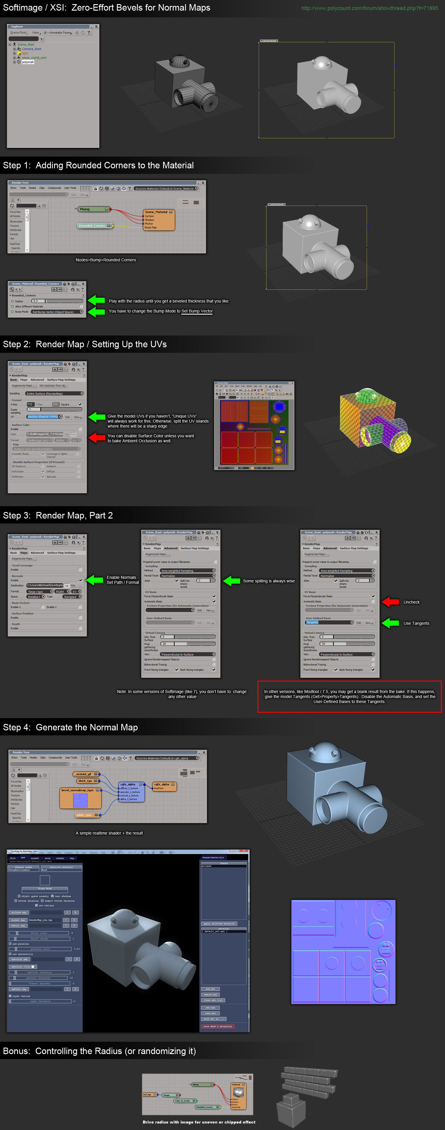
mental ray Round Corners Bump
The mental ray renderer offers an automatic bevel rendering effect called Round Corners Bump that can be baked into a normal map. This is available in 3ds Max, Maya, and XSI. See Zero Effort Beveling for normal maps - by Robert "r_fletch_r" Fletcher.
Jeff Patton posted about how to expose Round Corners Bump in 3ds Max so you can use it in other materials.
Michael "cryrid" Taylor posted a tutorial about how to use Round Corners in XSI.
XSI is able to bake a good normal map with it, but 3ds Max seems to bake it incorrectly, and Maya isn't able to bake the effect at all. Maybe Max might be able to bake it correctly, if the .mi shader is edited to use the correct coordinate space?