Normal map
What is a Normal Map?
A normal map is an image that stores a direction at each pixel. These directions are called normals.
The red, green, and blue channels of the image are used to control the direction of each pixel's normal.
A normal map is commonly used to fake high-resolution details on a low-resolution model. Each pixel of the map stores the surface slope of the original high-res mesh at that point. This creates the illusion of more surface detail or better curvature. However, the silhouette of the model doesn't change.
There are two basic methods to create normal maps. These methods can also be used together.
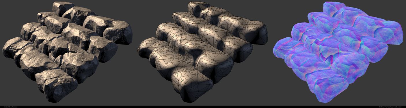
A normal mapped model, the mesh without the map, and the normal map alone.
Image by Eric Chadwick.

3D Workflow
The 3D workflow varies for each artist. See the following links for more information. In time this info will be condensed onto the wiki.
- Texture Baking has the step-by-step workflow for baking textures from a high-resolution model onto a lower-resolution model.
- A Practical Guide On Normal Mapping For Games has a detailed survey of normal mapping workflows.
High-Poly Modeling
- DigitalSculpting and/or Subdivision Surface Modeling are the usual technique for building high-poly models for baking normal maps.
- Optimize the high-resolution model to speed up bakes, to avoid running out of RAM while baking, and to keep 3d file sizes manageable. See Tools#Decimation_Software.
- If it's a sculpt reduce the vertex count to a manageable file size before exporting. Sculpting tools like Zbrush create triangles smaller than the bake pixels, which will increase baking time significantly without actually improving the bake.
- If it's a subdivision surface choose an appropriate resolution. Use just enough subdivisions to get a smooth surface at the baking resolution, and no more.
- Speeding up highpoly hard surface workflow
- Smooth Edge Shading - legitimate technique? - using a shader trick to fake high-poly rounded edges.
- Tip-Zero Effort Beveling for normal maps - the same trick.
Low-Poly Modeling
- Use ReTopologyModeling to build the lower-resolution in-game model.
- Good topology for baking: Normal_Map_Modeling#Low-Poly_Mesh and Understanding averaged normals and ray projection/Who put waviness in my normal map? and Skew you buddy! Making sense of skewed normal map details.
- Good topology for animation: Topology#Principles_of_Topology.
- The best kind of beveling ?
Texture Coordinates
- Create good Texture Coordinates for your low-poly model.
- For tangent-space normal mapping, split the UVs for every hard edge (where vertex normals are split, or different smoothing groups are used, same thing).
- You're making me hard. Making sense of hard edges, uvs, normal maps and vertex counts, and Earthquake on separating smoothing groups in the UV.
- 3ds Max: Flatten by Smoothing Group converts smoothing groups into UV islands. UV borders to hard edges creates the correct hard edges, even on seams within shells.
- Maya: Maya MEL Script help needed (UV border edges) converts hard edges into UV islands.
Triangulation
- See Texture Baking#Triangulation, and Polygon Count#Polygons Vs. Triangles.
- Triangulate before mirroring, to prevent shading errors.
Mirroring & Duplicating Parts
- If creating symmetrical parts, mirror the model. See Normal Map Modeling#Mirroring.
- Duplicate any model parts which reuse the same UV; this ensures perfect UV overlap.
- For using mirrored UVs, see JedTheKrampus on offsetting Mirrored UVs, Texture Baking#UV Coordinates.
Baking Tools
- Texture Baking
- Normal Map Bake Off: Xnormal vs 3Dsmax vs Substance Designer Bakes
- Official handplane support thread - Now freeware!!
- Future Xoliulshader support = why Xoliulshader doesn't work properly in 3ds Max 2013/2014.
Projection Errors
- Create an inflated copy of the low-resolution model, which encompasses the high-resolution model. See Texture Baking#Cages. Some tools create this automatically.
- Interpenetrating or close-together parts can cause baking artifacts, because neighboring surfaces will capture parts of each other, see Texture Baking#Solving Intersections. To "explode" means to separate the non-welded surfaces, mesh elements, Zbrush subtools, etc. so there is ample space between them. Use the same separation for the highpoly model and the lowpoly model. After the bake, move the pieces back together.
- If the modeling software has animation, you can keyframe the explode to easily reverse it after baking. Tools are also available, see Explode script needed (for baking purposes). Elements can be tagged by some baking tools, so specific low-poly elements will only bake related high-poly elements, this avoids exploding (3ds Max can use Material IDs, etc.).
- Understanding averaged normals and ray projection/Who put waviness in my normal map?
- Skew you buddy! Making sense of skewed normal map details.
- Skewmesh tutorial for Max and Xnormal by PeterK to prevent heavy distortions when baking with a cage, without the need to add extra supporting vertices.
- Of Bit Depths, Banding and Normal Maps.
Editing Maps
- Combine bakes if needed. See Ambient occlusion map#EarthQuake's Baking Method
- Add details from photos or other bakes. See RNM Normal Map Combiner, and Combine Normal (Polycount Forum thread).
- Some errors can be painted out, but avoid this! Any painting must be repeated if the model is re-baked, and painting on a normal map can introduce more artifacts.
- Swizzle. See Normal Map Technical Details#Common Swizzle Coordinates.
- Re-normalize. See Normal_map#Re-normalizing.
- Reduce to 8-bit. See Of Bit Depths, Banding and Normal Maps.
2D Workflow
Normal maps can be made in 2D painting software, without modeling in 3D. You can convert photo textures into normal maps, create node-based graphs to compile normal maps, or even hand-paint them with brushes.
Normal maps created in 2D work best when tiled across 3D models that have a uniform direction in tangent space, like terrains or walls. On these models the UVs are not rotated; they are all facing roughly in the same direction. To get seamless lighting, rotated UVs require specific gradients in the normal map, which can only be created properly by baking a 3D model.
A normal map baked from a high-poly mesh will often be better than one sampled from a texture, since you're rendering from a highly detailed surface. The normal map pixels will be recreating the surface angles of the high-poly mesh, resulting in a very believable look. A hybrid approach can be used by baking large and mid-level details from a high-poly mesh, and combining these with painted or photo-sourced "fine detail" for fabric weave, scratches, pores, etc.
Most image conversion tools assume the input is a heightmap, where black is low and white is high. If you try to convert a color texture that you've painted, the results are often very poor.
- Normal map process tutorial by Ben "poopinmymouth" Mathis includes an example of painting out wavy lines in a baked normal map.
Flat Color
The color (128,128,255) creates normals that are completely perpendicular to the polygon, as long as the vertex normals are also perpendicular. Remember a normal map's per-pixel normals create offsets from the vertex normals. If you want an area in the normal map to be flat, so it creates no offsets from the vertex normals, then use the color (128,128,255).
This becomes especially obvious when mirroring a normal map and using a shader with a reflection ingredient. Reflection tends to accentuate the angles between the normals, so any errors become much more apparent.

Image by Eric Chadwick
In a purely logical way, 127 seems like it would be the halfway point between 0 and 255. However 128 is the color that actually works in practice. When a test is done comparing (127,127,255) versus (128,128,255) it becomes obvious that 127 creates a slightly bent normal, and 128 creates a flat one.
This is because most game pipelines use unsigned normal maps. For details see the Polycount forum thread tutorial: fixing mirrored normal map seams.
Blending Normal Maps Together
Blending normal maps together is a quick way to add high-frequency detail like wrinkles, cracks, and the like. Fine details can be painted as a height map, then it can be converted into a normal map. Then this "details" normal map can be blended with a geometry-derived normal map.
Another use is to blend a high-frequency detail normal map overtop a lower-frequency one, for example on terrains, to get small details closeup and larger details in the distance.
Re-oriented Normal Mapping (RNM) is probably the most accurate method, and can be done in real-time. The Photoshop script Combine Normal by Vincent Callebaut uses this method, see the Polycount Forum thread Combine normal maps script for Photoshop. A full explanation is described on the page Blending in Detail - Self Shadow.
Below is a comparison of four other blending methods. Note that in these examples the default values were used for CrazyBump (Intensity 50, Strength 33, Strength 33), but the tool allows each layer's strength to be adjusted individually for stronger or milder results. Each of the normal maps below were re-normalized after blending.

|

|
| The blended normal maps. Image by Eric Chadwick |
Screenshot of the 3dsmax viewport, using the RTTNormalMap.fx shader. Image by Eric Chadwick |
The four blending methods used above:
- CrazyBump by Ryan Clark blends normal maps together using calculations in 3D space rather than just in 2D. This does probably the best job at preserving details, and each layer's strength settings can be tweaked individually.
- Combining Normal Maps in Photoshop by Rod Green blends normal maps together using Linear Dodge mode for the positive values and Difference mode for the negative values, along with a Photoshop Action to simplify the process. It's free, but the results may be less accurate than CrazyBump.
- Making of Varga by Paul "paultosca" Tosca blends normal maps together using Overlay mode for the red and green channels and Multiply mode for the blue channel. This gives a slightly stronger bump than the Overlay-only method. Leo "chronic" Covarrubias has a step-by-step tutorial for this method in CG Bootcamp Combine Normal Maps.
- Normal Map Deepening by Ben "poopinmymouth" Mathis shows how to blend normal maps together using Overlay mode. CGTextures tutorial for the NVIDIA Photoshop filter by Scott Warren also shows how to create normalmaps using multiple layers (Note: to work with the Overlay blend mode each layer's Output Level should be 128 instead of 255, you can use the Levels tool for this).
The Getting good height from Nvidia-filter normalizing grayscale height thread on the Polycount forum has a discussion of different painting/blending options. Also see the 2D Normal Map Tools section for painting and conversion tools.
Pre-Created Templates
A library of shapes can be developed and stored for later use, to save creation time for future normal maps. Things like screws, ports, pipes, and other doo-dads. These shapes can be stored as bitmaps with transparency so they can be layered into baked normal maps.
- Creating & Using NormalMap "Widgets" - by Steev "kobra" Kelly<
> How to set up and render template objects. - NormalMap Widget for 3ds Max - by Akram Parvez<
>A script to automate the setup and rendering process. - See the section Baking Transparency for more template-rendering tools and tutorials.
Re-normalizing
Re-normalizing means resetting the length of each normal in the map to 1.
A normal mapping shader takes the three color channels of a normal map and combines them to create the direction and length of each pixel's normal. These normals are then used to apply the scene lighting to the mesh. However if you edit normal maps by hand or if you blend multiple normal maps together this can cause those lengths to change. Most shaders expect the length of the normals to always be 1 (normalized), but some are written to re-normalize the normal map dynamically (for example, 3ds Max's Hardware Shaders do re-normalize).
If the normals in your normal map are not normalized, and your shader doesn't re-normalize them either, then you may see artifacts on the shaded surface... the specular highlight may speckle like crazy, the surface may get patches of odd shadowing, etc. To help you avoid this NVIDIA's normal map filter for Photoshop provides an easy way to re-normalize a map after editing; just use the Normalize Only option. Xnormal also comes with a Normalize filter for Photoshop.

Image by Scott Warren
Some shaders use compressed normal maps. Usually this means the blue channel is thrown away completely, so it's recalculated on-the-fly in the shader. However the shader has to re-normalize in order to recreate that data, so any custom normal lengths that were edited into the map will be ignored completely.
Ambient Occlusion into a Normal Map
If the shader doesn't re-normalize the normal map, an Ambient Occlusion Map can actually be baked into the normal map. This will shorten the normals in the crevices of the surface, causing the surface to receive less light there. This works with both diffuse and specular, or any other pass that uses the normal map, like reflection.
However it's usually best to keep the AO as a separate map (or in an alpha channel) and multiply it against the ambient lighting only. This is usually done with a custom shader. If you multiply it against the diffuse map or normal map then it also occludes diffuse lighting which can make the model look dirty. Ambient occlusion is best when it occludes ambient lighting only, for example a diffusely convolved cubemap.

Model by James Ku
To bake the AO into a normal map, adjust the levels of the AO layer first so the darks only go as low as 128 gray, then set the AO layer to Darken mode. This will shorten the normals in the normalmap, causing the surface to receive less light in the darker areas.
This trick doesn't work with any shaders that re-normalize, like 3ds Max's Hardware Shaders. The shader must be altered to actually use the lengths of your custom normals; most shaders just assume all normals are 1 in length because this makes the shader code simpler. Also this trick will not work with most of the common normal map compression formats, which often discard the blue channel and recalculate it in the shader, which requires re-normalization.
Back Lighting Example
You can customize normal maps for some interesting effects. If you invert the blue channel of a tangent-space map, the normals will be pointing to the opposite side of the surface, which can simulate backlighting.
 |

|
| Tree simulating subsurface scattering (front view). Image by Eric Chadwick |
Tree simulating subsurface scattering (back view). Image by Eric Chadwick |

| |
| The maps used for the leaves. The 2nd diffuse was simply color-inverted, hue-shifted 180°, and saturated. Image by Eric Chadwick | |
The tree leaves use a shader than adds together two diffuse maps, one using a regular tangent-space normal map, the other using the same normal map but with the blue channel inverted. This causes the diffuse map using the regular normal map to only get lit on the side facing the light (front view), while the diffuse map using the inverted normal map only gets lit on the opposite side of the leaves (back view). The leaf geometry is 2-sided but uses the same shader on both sides, so the effect works no matter the lighting angle. As an added bonus, because the tree is self-shadowing the leaves in shadow do not receive direct lighting, which means their backsides do not show the inverted normal map, so the fake subsurface scatter effect only appears where the light directly hits the leaves. This wouldn't work for a whole forest because of the computational cost of self-shadowing and double normal maps, but could be useful for a single "star" asset, or if LODs switched the distant trees to a model that uses a cheaper shader.
2D Normal Map Tools
- Combine Normal is a Photoshop script for Re-oriented Normal Mapping (RNM), see the Polycount Forum thread Combine normal maps script for Photoshop, and the page Blending in Detail - Self Shadow.
- CrazyBump is a commercial normal map converter.
- ShaderMap is a commercial normal map converter.
- PixPlant is a commercial normal map converter.
- NJob is a free normal map converter.
- NVIDIA normalmap filter for Photoshop is a free normal map converter.
- Xnormal height-to-normals filter for Photoshop is a free normal map converter.
- NDO
- Filter Forge
- Substance Designer
Older Tutorials
A word of warning: There is a huge amount of misinformation about normal mapping on the web. It is best to assume all tutorials are incorrect, until you can verify the results yourself with your own tools and models.
- The Generation and Display of Normal Maps in 3ds Max (500kb PDF) <
> Excellent whitepaper from Autodesk about normal mapping in 3ds Max and other apps. - Renderbump and baking normal maps from high poly models using Blender 3D by "katsbits"<
>Baking normal maps in Blender. - Techniques for Creating Normal Maps in the Unreal Developer Network's Unreal Engine 3 section contains advice from Epic Games artists on creating normal maps for UE3. The Design Workflow page has a summary.
- Creating Models in Quake 4 by Raven Software is a comprehensive guide to creating Quake 4 characters.
- Normalmaps for the Technical Game Modeler by Ariel Chai shows how low-poly smoothing and UVs can affect normal maps in Doom 3.
- 3DTutorials/Modeling_High-Low_Poly_Models_for_Next_Gen_Games by João "Masakari" Costa is an overview of modeling for normal maps.
- The Beveling section on the Tech-Artists.Org Wiki discusses how smoothing groups and bevels affect the topology of the low-poly model.
- The two-part article Beautiful, Yet Friendly by Guillaume Provost explains how smoothing groups and other mesh attributes cause vertices to be duplicated in the game. The vertex count is actually what matters in-game, not the triangle or poly count.
- Normal map workflow by Ben "poopinmymouth" Mathis demonstrates his normal mapping workflow in 3ds Max and Photoshop.
- This video tutorial by Jeff "airbrush" Ross shows in Maya how to subdivide the low-poly mesh so it more closely matches the high-poly mesh, to help solve wavy lines in the bake.
- Normal Mapping Tutorial by Ben Cloward is a comprehensive tutorial about the entire normal map creation process.
- Generating High Fidelity Normal Maps with 3-D Software by Dave McCoy shows how to use a special lighting setup to render normal maps (instead of baking them).
- Tutorial for the NVIDIA Photoshop filter by Scott Warren shows how to create deep normal maps using multiple layers. Note: to use Overlay blend mode properly, make sure to change each layer's Levels Output Level to 128 instead of 255.
- Normalmap Deepening by Ben "poopinmymouth" Mathis shows how to adjust normal maps, and how to layer together painted and baked normal maps.
- Tutorial for painting out seams on mirrored tangent-space normal maps by warby helps to solve seams along horizontal or vertical UV edges, but not across angled UVs.
- Cinema 4D and Normal Maps For Games by James Hastings-Trew describes normal maps in plain language, with tips on creating them in Cinema 4D.
- 3ds Max normal mapping overview by Alan Noon is a great thread on CGTalk about the normal mapping process.
- Hard Surface Texture Painting by Stefan Morrell is a good introduction to painting textures for metal surfaces.
More Information
- Curvature map
- DuDv map
- Flow map
- Normal Map Modeling
- Normal Map Technical Details
- Radiosity normal map
- Texture Baking
- Vector displacement map