Difference between revisions of "Normal map"
(Talk) |
EricChadwick (Talk | contribs) (WikiName) |
||
| Line 1: | Line 1: | ||
| − | + | <!-- ## page was renamed from Normal Map --> | |
| − | + | * [[Polycount|Main Page]] > [[Category:Texturing]] > [[Normal Map]] | |
| − | + | = Normal Map = | |
| − | A normal map | + | <span id="WhatIsANormalMap"></span><span id="WIANM"></span> |
| + | == What is a Normal Map? == | ||
| + | A Normal Map is usually used to fake high-res geometry detail when it's mapped onto a low-res mesh. The pixels of the normal map each store a ''normal'', a vector that describes the surface slope of the original high-res mesh at that point. The red, green, and blue channels of the normal map are used to control the direction of each pixel's normal. | ||
| − | + | When a normal map is applied to a low-poly mesh, the texture pixels control the direction each of the pixels on the low-poly mesh will be facing in 3D space, creating the illusion of more surface detail or better curvature. However, the silhouette of the model doesn't change. | |
| + | {| border="1" cellpadding="2" cellspacing="0" | ||
| + | | [[Image:NormalMap$Whatif_normalmap_mapped2.jpg]] | ||
| + | | [[Image:NormalMap$Whatif_normalmap_low.jpg]] | ||
| + | |- | ||
| + | | A model with a normal map.<<BR>><span style="font-size: smaller">image by [http://www.3dartisan.net/~kuman/ James Ku]</span> | ||
| + | | The low-resolution wireframe.<<BR>><span style="font-size: smaller">image by [http://www.3dartisan.net/~kuman/ James Ku]</span> | ||
| + | |} | ||
| + | |||
| + | |||
| + | |||
| + | <span id="TSVOS"></span><<Anchor([[TangentSpaceVsObjectSpace]])>> | ||
| + | == Tangent-Space vs. Object-Space == | ||
| + | Normal maps can be made in either of two basic flavors: tangent-space or object-space. Object-space is also called local-space or model-space, same thing. World-space is basically the same as object-space, except it requires the model to remain in its original orientation, neither rotating nor deforming, so it's almost never used. | ||
| + | |||
| + | <span id="TSNM"></span> | ||
| + | === Tangent-space normal map === | ||
| + | {| border="1" cellpadding="2" cellspacing="0" | ||
| + | |- | ||
| + | |} | ||
| + | Predominantly-blue colors. Object can rotate and deform. Good for deforming meshes, like characters, animals, flags, etc. | ||
| + | <<BR>> | ||
| + | <<BR>> [[Image:NormalMap$green_plus.png]] Maps can be reused easily, like on differently-shaped meshes. | ||
| + | <<BR>> [[Image:NormalMap$green_plus.png]] Maps can be tiled and mirrored easily, though some games might not support [[#M|mirroring]] very well. | ||
| + | <<BR>> [[Image:NormalMap$green_plus.png]] Easier to [[#BlendingNormalMapsTogether|overlay painted details]]. | ||
| + | <<BR>> [[Image:NormalMap$green_plus.png]] Easier to use [[#NormalMapCompression|image compression]]. | ||
| + | <<BR>> [[Image:NormalMap$red_x.png]] More difficult to avoid smoothing problems from the low-poly vertex normals (see [[#SmoothingGroupsAndHardEdges|Smoothing Groups and Hard Edges]]). | ||
| + | <<BR>> [[Image:NormalMap$red_x.png]] Slightly slower performance than an object-space map (but not by much). | ||
| + | |||
| + | <span id="OSNM"></span> | ||
| + | === Object-space normal map === | ||
| + | {| border="1" cellpadding="2" cellspacing="0" | ||
| + | |- | ||
| + | |} | ||
| + | Rainbow colors. Objects can rotate, but usually shouldn't be deformed, unless the shader has been modified to support deformation. | ||
| + | <<BR>> | ||
| + | <<BR>> [[Image:NormalMap$green_plus.png]] Easier to generate high-quality curvature because it completely ignores the crude smoothing of the low-poly vertex normals. | ||
| + | <<BR>> [[Image:NormalMap$green_plus.png]] Slightly better performance than a tangent-space map (but not by much). | ||
| + | <<BR>> [[Image:NormalMap$red_x.png]] Can't easily reuse maps, different mesh shapes require unique maps. | ||
| + | <<BR>> [[Image:NormalMap$red_x.png]] Difficult to tile properly, and mirroring requires [http://boards.polycount.net/showthread.php?t=53986 specific shader support]. | ||
| + | <<BR>> [[Image:NormalMap$red_x.png]] Harder to [[#BlendingNormalMapsTogether|overlay painted details]] because the base colors vary across the surface of the mesh. Painted details must be converted into Object Space to be combined properly with the OS map. | ||
| + | <<BR>> [[Image:NormalMap$red_x.png]] They don't [[#NormalMapCompression|compress]] very well, since the blue channel can't be recreated in the shader like with tangent-space maps. Also the three color channels contain very different data which doesn't compress well, creating many artifacts. Using a half-resolution object-space map is one option. | ||
| + | |||
| + | <span id="CBS"></span><<Anchor([[ConvertingBetweenSpaces]])>> | ||
| + | === Converting Between Spaces === | ||
| + | Normal maps can be converted between tangent space and object space, in order to use them with different blending tools and shaders, which require one type or the other. | ||
| + | |||
| + | [http://diogo.codingcorner.net Diogo "fozi" Teixeira] created a tool called [http://boards.polycount.net/showthread.php?p=1072599#post1072599 NSpace] that converts an object-space normal map into a tangent-space map, which then works seamlessly in the Max viewport. He converts the map by using the same tangent basis that 3ds Max uses for its hardware shader. To see the results, load the converted map via the ''Normal Bump'' map and enable "Show Hardware Map in Viewport". [http://gameartist.nl/ Osman "osman" Tsjardiwal] created a GUI for NSpace, you can [http://boards.polycount.net/showthread.php?p=1075143#post1075143 download it here], just put it in the same folder as the NSpace exe and run it. Diogo has further [http://boards.polycount.net/showthread.php?p=1074160#post1074160 plans for the tool] as well. | ||
| + | |||
| + | {| border="1" cellpadding="2" cellspacing="0" | ||
| + | |- | ||
| + | |} | ||
| + | |||
| + | [http://www.linkedin.com/in/earthquake Joe "EarthQuake" Wilson] said: "[8Monkey Labs has] a tool that lets you load up your reference mesh and object space map. Then load up your tangent normals, and adjust some sliders for things like tile and amount. We need to load up a mesh to know how to correctly orient the tangent normals or else things will come out upside down or reverse etc. It mostly works, but it tends to "bend" the resulting normals, so you gotta split the mesh up into some smoothing groups before you run it, and then I usually will just composite this "combo" texture over my orig map in Photoshop." | ||
| + | |||
| + | <span id="RGBC"></span><span id="RGBChannels"></span> | ||
== RGB Channels == | == RGB Channels == | ||
| + | Shaders can use different techniques to render tangent-space normal maps, but the normal map directions are usually consistent within a game. Usually the red channel of a tangent-space normal map stores the X axis (pointing the normals predominantly leftwards or rightwards), the green channel stores the Y axis (pointing the normals predominantly upwards or downwards), and the blue channel stores the Z axis (pointing the normals outwards away from the surface). | ||
| + | {| border="1" cellpadding="2" cellspacing="0" | ||
| + | |- | ||
| + | |} | ||
| + | |||
| + | If you see lighting coming from the wrong angle when you're looking at your normal-mapped model, and the model is using a tangent-space normal map, the normal map shader might be expecting the red or green channel (or both) to point in the opposite direction. To fix this either change the shader, or simply invert the appropriate color channels in an image editor, so that the black pixels become white and the white pixels become black. | ||
| + | |||
| + | Some shaders expect the color channels to be swapped or re-arranged to work with a particular [[#NormalMapCompression|compression format]]. For example the DXT5_nm format usually expects the X axis to be in the alpha channel, the Y axis to be in the green channel, and the red and blue channels to be empty. | ||
| + | |||
| + | <span id="TB"></span><<Anchor([[TangentBasis]])>> | ||
| + | == Tangent Basis == | ||
| + | [[#TangentSpaceVsObjectSpace|Tangent-space]] normal maps use a special kind of vertex data called the ''tangent basis''. This is similar to UV coordinates except it provides directionality across the surface, it forms a surface-relative coordinate system for the per-pixel normals stored in the normal map. | ||
| + | |||
| + | Light rays are in world space, but the normals stored in the normal map are in tangent space. When a normal-mapped model is being rendered, the light rays must be converted from world space into tangent space, using the tangent basis to get there. At that point the incoming light rays are compared against the directions of the normals in the normal map, and this determines how much each pixel of the mesh is going to be lit. Alternatively, instead of converting the light rays some shaders will convert the normals in the normal map from tangent space into world space. Then those world-space normals are compared against the light rays, and the model is lit appropriately. The method depends on who wrote the shader, but the end result is the same. | ||
| + | |||
| + | Unfortunately for artists, there are many different ways to calculate the tangent basis: [http://area.autodesk.com/blogs/chris/how_the_3ds_max_scanline_renderer_computes_tangent_and_binormal_vectors_for_normal_mapping 3ds Max], [http://download.autodesk.com/us/maya/2011help/index.html?url=./files/Appendix_A_Tangent_and_binormal_vectors.htm,topicNumber=d0e227193 Maya], [http://www.codesampler.com/dx9src/dx9src_4.htm#dx9_dot3_bump_mapping DirectX 9], [http://developer.nvidia.com/object/NVMeshMender.html NVMeshMender], [http://www.terathon.com/code/tangent.html Eric Lengyel], a custom solution, etc. This means a normal map baked in one application probably won't shade correctly in another. Artists must do some testing with different [[#T|baking tools]] to find which works best with their output. When the renderer (or game engine) renders your game model, [[#ShadersAndSeams|the shader]] must use the same tangent basis as the normal map baker, otherwise you'll get incorrect lighting, especially across the seams between UV shells. | ||
| + | |||
| + | The [http://www.xnormal.net/ xNormal] SDK supports custom tangent basis methods. When a programmer uses it to implement their renderer's own tangent basis, artists can then use Xnormal to bake normal maps that will match their renderer perfectly. | ||
| + | |||
| + | The [[#UVC|UVs]] and the [[#SGAHE|vertex normals]] on the low-res mesh directly influence the coloring of a [[#TSNM|tangent-space]] normal map when it is baked. Each tangent basis vertex is a combination of three things: the mesh vertex's normal (influenced by smoothing), the vertex's tangent (usually derived from the V texture coordinate), and the vertex's bitangent (derived in code, also called the binormal). These three vectors create an axis for each vertex, giving it a specific orientation in the tangent space. These axes are used to properly transform the incoming lighting from world space into tangent space, so your normal-mapped model will be lit correctly. | ||
| + | |||
| + | When a triangle's vertex normals are pointing straight out, and a pixel in the normal map is neutral blue (128,128,255) this means that pixel's normal will be pointing straight out from the surface of the low-poly mesh. When that pixel normal is tilted towards the left or the right in the tangent coordinate space, it will get either more or less red color, depending on whether the normal map is set to store the X axis as either a positive or a negative value. Same goes for when the normal is tilted up or down in tangent space, it will either get more or less green color. If the vertex normals aren't exactly perpendicular to the triangle, the normal map pixels will be tinted away from neutral blue as well. The vertex normals and the pixel normals in the normal map are combined together to create the final per-pixel surface normals. | ||
| + | |||
| + | [[#SAS|Shaders]] are written to use a particular direction or "handedness" for the X and Y axes in a normal map. Most apps tend to prefer +X (red facing right) and +Y (green facing up), while others like 3ds Max prefer +X and -Y. This is why you often need to invert the green channel of a normal map to get it to render correctly in this or that app... the shader is expecting a particular handedness. | ||
| + | |||
| + | {| border="1" cellpadding="2" cellspacing="0" | ||
| + | |- | ||
| + | |} | ||
| + | |||
| + | When you look at a tangent-space normal map for a character, you typically see different colors along the UV seams. This is because the UV shells are often oriented at different angles on the mesh, a necessary evil when translating the 3D mesh into 2D textures. The body might be mapped with a vertical shell, and the arm mapped with a horizontal one. This requires the normals in the normal map to be twisted for the different orientations of those UV shells. The UVs are twisted, so the normals must be twisted in order to compensate. The tangent basis helps reorient (twist) the lighting as it comes into the surface's local space, so the lighting will then look uniform across the normal mapped mesh. | ||
| + | |||
| + | When an artist tiles a tangent-space normal map across an arbitrary mesh, like a landscape, this tends to shade correctly because the mesh has a uniform direction in tangent space. If the mesh has discontinuous UV coordinates (UV seams), or the normal map has large directional gradients across it, the tangent space won't be uniform anymore so the surface will probably have shading seams. | ||
| + | |||
| + | {| border="1" cellpadding="2" cellspacing="0" | ||
| + | |- | ||
| + | |- | ||
| + | |- | ||
| + | |- | ||
| + | |- | ||
| + | |} | ||
| + | |||
| + | <span id="MTLPM"></span> | ||
| + | == Modeling the Low-Poly Mesh == | ||
| + | The in-game mesh usually needs to be carefully optimized to create a good silhouette, define edge-loops for better deformation, and minimize extreme changes between the vertex normals for better shading (see [[#SmoothingGroupsAndHardEdges|Smoothing Groups & Hard Edges]]). | ||
| + | |||
| + | In order to create an optimized in-game mesh including a good silhouette and loops for deforming in animation, you can start with the 2nd subdivision level of your [[Digital Sculpting|digital sculpt]], or in some cases with the base mesh itself. Then you can just collapse edge loops or cut in new edges to add/remove detail as necessary. Or you can [[Digital Sculpting#OART|re-toplogize]] from scratch if that works better for you. | ||
| + | |||
| + | <span id="UVC"></span><span id="UVCoordinates"></span> | ||
| + | === UV Coordinates === | ||
| + | Normal map baking tools only capture normals within the 0-1 UV square, any UV bits outside this area are ignored. | ||
| + | |||
| + | Only one copy of the forward-facing UVs should remain in the 0-1 UV square at baking time. If the mesh uses overlapping UVs, this will likely cause artifacts to appear in the baked map, since the baker will try render each UV shell into the map. Before baking, it's best to move all the overlaps and mirrored bits outside the 0-1 sqaure. | ||
| + | |||
| + | {| border="1" cellpadding="2" cellspacing="0" | ||
| + | |- | ||
| + | |} | ||
| + | |||
| + | If you move all the overlaps and mirrored bits exactly 1 UV unit (any whole number will do), then you can leave them there after the bake and they will still be mapped correctly. You can move them back if you want, it doesn't matter to most game engines. Be aware that ZBrush does use UV offsets to manage mesh visibility, however this usually doesn't matter because the ZBrush cage mesh is often a different mesh than the in-game mesh used for baking. | ||
| + | |||
| + | You should avoid changing the UVs after baking the normal map, because rotating or mirroring UVs after baking will cause the normal map not to match the [[#TB|tangent basis]] anymore, which will likely cause lighting problems. | ||
| + | |||
| + | In 3ds Max, W is a third texture coordinate. It's used for 3D procedural textures and for storing vertex color in UV channels (you need 3 axes for RGB, so UVW can store vertex color). Bake problems can be avoided by moving any overlapping UVs to -1 on the W axis, with the same results as moving them 1 unit on the U or V axes. The tool Render To Texture will always bake whatever UVs are the highest along the W axis. However using W can be messy... it's generally hidden unless you purposefully look for it (bad for team work), doesn't get preserved on export to other apps, and high W values can prevent selecting and/or welding UVs. | ||
| + | |||
| + | <span id="M"></span><span id="Mirroring"></span> | ||
| + | === Mirroring === | ||
| + | Normal maps can be mirrored across a model to create symmetrical details, and save UV space, which allows more detail in the normal map since the texture pixels are smaller on the model. | ||
| + | |||
| + | With [[#OSNM|object-space]] maps, mirroring requires [http://boards.polycount.net/showthread.php?t=53986 specific shader support]. For [[#TSNM|tangent-space]] maps, mirroring typically creates a shading seam, but this can be reduced or hidden altogether, depending on the method used. | ||
| + | |||
| + | <span id="TMW"></span> | ||
| + | ==== Typical Mirroring Workflow ==== | ||
| + | # Delete the mesh half that will be mirrored. | ||
| + | # Arrange the UVs for the remaining model, filling the UV square. | ||
| + | # Mirror the model to create a "whole" mesh, welding the mesh vertices along the seam. | ||
| + | # Move the mirrored UVs exactly 1 unit (or any whole number) out of the 0-1 UV square. | ||
| + | # Bake the normal map. | ||
| + | |||
| + | Sometimes an artist will decide to delete half of a symmetrical model before baking. | ||
| + | |||
| + | This is a mistake however because often the vertex normals along the hole will bend towards the hole a bit; there are no faces on the other side to average the normals with. This will create a strong lighting seam in the normal map. | ||
| + | |||
| + | It's typically best to use the complete mirrored model to bake the normal map, not just the unique half. | ||
| + | |||
| + | To prevent the mirrored UVs from causing overlaps or baking errors, move the mirrored [[#UVC|UVs]] out of the 0-1 UV space, so only one copy of the non-mirrored UVs is left within the 0-1 square. | ||
| + | |||
| + | To avoid texel "leaks" between the UV shells, make sure there's enough [[Edge Padding]] around each shell, including along the edges of the normal map. None of the UV shells should be touching the edge of the 0-1 UV square, unless they're meant to tile with the other side of the map. | ||
| + | |||
| + | <span id="CM"></span> | ||
| + | ==== Center Mirroring ==== | ||
| + | If the mirror seam runs along the surface of a continuous mesh, like down the center of a human face for example, then it will probably create a lighting seam. | ||
| + | |||
| + | In Epic Games' [http://www.unrealtechnology.com/technology.php Unreal Engine 3] (UE3) their symmetrical models commonly use centered mirroring. Epic uses materials that mix [[Detail Map]]s with the normal maps; these seem to scatter the diffuse/specular lighting and help minimize the obviousness of the mirror seams. For their [[Light Map]]ped models they use [http://udn.epicgames.com/Three/LightMapUnwrapping.html a technique] that can almost completely hide the mirror seam. | ||
| + | |||
| + | {| border="1" cellpadding="2" cellspacing="0" | ||
| + | |- | ||
| + | |} | ||
| + | |||
| + | '''''[http://www.zbrushcentral.com/showpost.php?p=573108&postcount=28 GOW2 normal map seams], [http://utforums.epicgames.com/showthread.php?p=27166791#post27166791 UDK normal map seams]''''' | ||
| + | |||
| + | <span id="OM"></span> | ||
| + | ==== Offset Mirroring ==== | ||
| + | Offset mirroring is a method where you move the mirror seam off to one side of the model, so the seam doesn't run exactly down the center. For example with a character's head, the UV seam can go down along the side of the head in front of the ear. The UV shell for the nearest ear can then be mirrored to use the area on the other side of the head. | ||
| + | |||
| + | This avoids the "Rorschach" effect and allows non-symmetrical details, but it still saves texture space because the two sides of the head can be mirrored (they're never seen at the same time anyhow). | ||
| + | |||
| + | Offset mirroring doesn't get rid of the seam, but it does move it off to a place where it can either be less obvious, or where it can be hidden in a natural seam on the model. | ||
| + | |||
| + | <span id="FCM"></span> | ||
| + | ==== Flat Color Mirroring ==== | ||
| + | [http://boards.polycount.net/showthread.php?t=51088 Tutorial for painting out seams on mirrored tangent-space normal maps] by [http://www.warbeast.de/ warby] solves seams by painting a flat set of normals along the seam, using neutral blue (128,128,255). However it only works along horizontal or vertical UV seams, not across any angled UVs. It also removes any details along the mirror seam, creating blank areas. | ||
| + | |||
| + | <span id="EM"></span> | ||
| + | ==== Element Mirroring ==== | ||
| + | The mirror seam can be avoided completely when it doesn't run directly through any mesh. For example if there's a detached mesh element that runs down the center of the model, this can be uniquely mapped, while the meshes on either side can be mirrors of each other. Whenever the mirrored parts don't share any vertex normals with the non-mirrored parts, there won't be any seams. | ||
| + | |||
| + | {| border="1" cellpadding="2" cellspacing="0" | ||
| + | |- | ||
| + | |} | ||
| + | |||
| + | <span id="SGAHE"></span> | ||
| + | <<Anchor([[SmoothingGroupsAndHardEdges]])>> | ||
| + | === Smoothing Groups & Hard Edges === | ||
| + | |||
| + | Each vertex in a mesh has at least one vertex normal. These normals are used to light the triangles of the mesh. Each vertex however can have more than one normal, as many as the number of triangles connected to it. When two triangles have different vertex normals along their shared edge, it creates a shading seam, called a ''hard edge'' in most modeling apps. 3ds Max uses ''Smoothing Groups'' to get the same result... creating hard and soft edges by splitting and combining vertex normals. | ||
| + | |||
| + | {| border="1" cellpadding="2" cellspacing="0" | ||
| + | |- | ||
| + | |} | ||
| + | |||
| + | If the mesh uses all soft normals (a single smoothing group) this can produce extreme shading differences across the model, as the lighting is interpolated across the extreme differences between the vertex normals. It is best to reduce these extremes when you can because the [[#TangentBasis|tangent basis]] can only do so much to counteract it. | ||
| + | |||
| + | Hard edges are usually best where the model already has a natural seam. For example, you can add a hard edge along the rim of a car's wheel well, to prevent the inside of the wheel well from distorting the shading for the outside of the car body. Mechanical models usually need hard edges where ever the surface bends more than about 45 degrees. | ||
| + | |||
| + | For most meshes, the best results usually come from adding hard edges where ever there are UV seams. There are no hard rules however, you must experiment with different approaches to find what works best in your game. | ||
| + | |||
| + | When you use object-space normal maps the vertex normal problem goes away since you're no longer relying on the crude vertex normals of the mesh. An object-space normal map completely ignores vertex normals. Object-space mapping allows you to use all soft edges and no bevels on the low-res mesh, without showing lighting errors. | ||
| + | |||
| + | <span id="HEDAT"></span> | ||
| + | ==== Hard Edge Discussions & Tutorials ==== | ||
| + | * [http://www.polycount.com/forum/showthread.php?t=73593 Normal Maps: Can Somone Explain This "Black Edge" issue] | ||
| + | * [http://www.polycount.com/forum/showthread.php?t=73566 Normal Maps: Can someone explain normals, tangents and split UVs?] | ||
| + | * [http://www.polycount.com/forum/showthread.php?t=72861 3Point Shader Lite - Shader material editor and Quality Mode normalmaps for 3ds Max] | ||
| + | * [http://boards.polycount.net/showthread.php?t=68173 Why you should NOT trust 3ds Max's viewport normal-map display!] | ||
| + | * [http://www.game-artist.net/forums/support-tech-discussion/10503-xsi-normal-mapped-cube-looks-bad.html XSI - normal mapped cube looks bad] | ||
| + | * [http://www.game-artist.net/forums/support-tech-discussion/11924-weird-maya-normal-map-seam-artifact-problem-am-i-making-simple-mistake.html Weird Maya normal map seam/artifact problem] | ||
| + | * [http://boards.polycount.net/showthread.php?p=1080600 Seams in Normals when Creating Tiling Environment Trims and other Tiles] | ||
| + | * The tutorial [http://www.svartberg.com/tutorials/article_normalmaps/normalmaps.html Normalmaps for the Technical Game Modeler] by [http://www.svartberg.com Ariel Chai] shows how low-poly smoothing can affect the normal map. | ||
| + | * The tutorial: [http://wiki.polycount.net/3D_Tutorials/Modeling_High-Low_Poly_Models_for_Next_Gen_Games Modeling High/Low Poly Models for Next Gen Games] by [http://www.acetylenegames.com/artbymasa/ João "Masakari" Costa] shows how smoothing affects raycasting. | ||
| + | * The [http://tech-artists.org/wiki/Beveling Beveling section on the Tech-Artists.Org Wiki] discusses the breaking of normals and smoothing groups in general terms. | ||
| + | * The two-part article [http://www.ericchadwick.com/examples/provost/byf2.html#wts Beautiful, Yet Friendly] by [http://www.linkedin.com/in/gprovost Guillaume Provost] explains how smoothing groups and other mesh attributes cause vertices to be duplicated in the game. The vertex count is actually what matters in the game, not the triangle count. | ||
| + | * The Crysis documentation [http://doc.crymod.com/AssetCreation/PolyBumpReference.html PolyBump Reference] has a section towards the bottom that shows how smoothing affects their baked normal maps. | ||
| + | * The polycount thread [http://boards.polycount.net/showthread.php?t=60694 Toying around with normal map approaches] has a great discussion of how best to use smoothing groups and bevels for better shading. | ||
| + | |||
| + | <span id="UB"></span> | ||
| + | ==== Using Bevels ==== | ||
| + | Bevels/chamfers generally improve the silhouette of the model, and can also help reflect specular highlights better. | ||
| + | |||
| + | However bevels tend to produce long thin triangles, which slow down the in-game rendering of your model. Real-time renderers have trouble rendering long thin triangles because they create a lot of sub-pixel areas to render. | ||
| + | |||
| + | Bevels also balloon the vertex count, which can increase the transform cost and memory usage. Hard edges increase the vertex count too, but not when the edge also shares a seam in UV space. For a good explanation of the vertex count issue, see [http://www.ericchadwick.com/examples/provost/byf2.html#wts Beautiful, Yet Friendly]. | ||
| + | |||
| + | Using hard edges with matching UV shells tends to give better performance and better cosmetic results than using bevels. However there are differing opinions on this, see the Polycount thread "[http://boards.polycount.net/showthread.php?t=71760 Maya transfer maps help]". | ||
| + | |||
| + | <span id="EVN"></span> | ||
| + | ==== Edited Vertex Normals ==== | ||
| + | If you use bevels the shading will be improved by editing the vertex normals so the larger flat surfaces have perpendicular normals. The vertex normals are then forced to blend across the smaller bevel faces, instead of across the larger faces. See the Polycount thread [http://boards.polycount.net/showthread.php?t=66139 Superspecular soft edges tutorial chapter 1]. | ||
| + | |||
| + | {| border="1" cellpadding="2" cellspacing="0" | ||
| + | |- | ||
| + | |} | ||
| + | |||
| + | <span id="MTHPM"></span><<Anchor([[ModelingTheHighPolyMesh]])>> | ||
| + | == Modeling The High-Poly Mesh == | ||
| + | [[Subdivision Surface Modeling]] and [[Digital Sculpting]] are the techniques most often used for modeling a normal map. | ||
| + | |||
| + | Some artists prefer to model the in-game mesh first, other artists prefer to model the high-res mesh first, and others start somewhere in the middle. The modeling order is ultimately a personal choice though, all three methods can produce excellent results: | ||
| + | * Build the in-game model, then up-res it and sculpt it. | ||
| + | * Build and sculpt a high resolution model, then build a new in-game model around that. | ||
| + | * Build a basemesh model, up-res and sculpt it, then step down a few levels of detail and use that as a base for building a better in-game mesh. | ||
| + | If the in-game mesh is started from one of the subdivision levels of the basemesh sculpt, various edge loops can be collapsed or new edges can be cut to add/remove detail as necessary. | ||
| + | |||
| + | <span id="SE"></span> | ||
| + | === Sloped Extrusions === | ||
| + | {| border="1" cellpadding="2" cellspacing="0" | ||
| + | |- | ||
| + | |} | ||
| + | |||
| + | See also [[3D Tutorials/Modeling High-Low Poly Models for Next Gen Games|Modeling High/Low Poly Models for Next Gen Games]] by [http://www.acetylenegames.com/artbymasa/ João "Masakari" Costa] | ||
| + | |||
| + | <span id="MRF"></span><span id="MRRCB"></span> | ||
| + | === mental ray Round Corners Bump === | ||
| + | The mental ray renderer offers an automatic bevel rendering effect called Round Corners Bump that can be baked into a normal map. This is available in 3ds Max, Maya, and XSI. See [http://boards.polycount.net/showthread.php?t=71995 Zero Effort Beveling for normal maps] - by [http://boards.polycount.net/member.php?u=31662 Robert "r_fletch_r" Fletcher]. | ||
| + | |||
| + | [http://jeffpatton.net/ Jeff Patton] posted about [http://jeffpatton.cgsociety.org/blog/archive/2007/10/ how to expose Round Corners Bump] in 3ds Max so you can use it in other materials. | ||
| + | |||
| + | [http://cryrid.com/art/ Michael "cryrid" Taylor] posted a tutorial about how to use [http://cryrid.com/images/temp/XSI/zeroeffort_bevels.jpg Round Corners in XSI]. | ||
| + | |||
| + | XSI is able to bake a good normal map with it, but 3ds Max seems to bake it incorrectly, and Maya isn't able to bake the effect at all. Maybe Max might be able to bake it correctly, if the .mi shader is edited to use the correct coordinate space? | ||
| + | |||
| + | <span id="Baking"></span> | ||
| + | <span id="B"></span> | ||
| + | == Baking == | ||
| + | The process of transferring normals from the high-res model to the in-game model is often called baking. The baking tool usually starts projecting a certain numerical distance out from the low-poly mesh, and sends rays inwards towards the high-poly mesh. When a ray intersects the high-poly mesh, it records the mesh's surface normal and saves it in the normal map. | ||
| + | |||
| + | To get an understanding of how all the options affect your normal map, do some test bakes on simple meshes like boxes. They generate quickly so you can experiment with [[#UVCoordinates|UV mirroring]], [[#SGAHE|smoothing groups]], etc. This helps you learn the settings that really matter. | ||
| + | * The tutorial [http://wiki.polycount.net/3D_Tutorials/Modeling_High-Low_Poly_Models_for_Next_Gen_Games Modeling High/Low Poly Models for Next Gen Games] by [http://www.acetylenegames.com/artbymasa/ João "Masakari" Costa] has more examples of ray-casting, plus how to get better results from the bake. | ||
| + | |||
| + | <span id="RT"></span> | ||
| + | === Reset Transforms === | ||
| + | Before baking, make sure your low-poly model's transforms have been reset. '''''This is very important!''''' Often during the modeling process a model will be rotated and scaled, but these compounded transforms can create a messy local "space" for the model, which in turn often creates rendering errors for normal maps. | ||
| + | |||
| + | In 3ds Max, use the Reset Xforms utility then Collapse the Modifier Stack. In Maya use Freeze Transformation. In XSI use the Freeze button. | ||
| + | |||
| + | <span id="TRI"></span> | ||
| + | === Triangulating === | ||
| + | Before baking, it is usually best to triangulate the low-poly model, converting it from polygons into pure triangles. This prevents the vertex normals from being changed later on, which can create specular artifacts. | ||
| + | |||
| + | {| border="1" cellpadding="2" cellspacing="0" | ||
| + | |- | ||
| + | |} | ||
| + | |||
| + | Sometimes a baking tool or a mesh exporter/importer will re-triangulate the polygons. A quad polygon is actually treated as two triangles, and the internal edge between them is often switched diagonally during modeling operations. When the vertices of the quad are moved around in certain shapes, the software's algorithm for polygon models tries to keep the quad surface in a "rational" non-overlapping shape. It does this by switching the internal edge between its triangles. | ||
| + | |||
| + | {| border="1" cellpadding="2" cellspacing="0" | ||
| + | |- | ||
| + | |} | ||
| + | |||
| + | <span id="WWC"></span> | ||
| + | <<Anchor([[WorkingWithCages]])>> | ||
| + | === Working with Cages === | ||
| + | ''Cage'' has two meanings in the normal-mapping process: a low-poly base for [[subdivision surface modeling]] (usually called the [[Digital Sculpting#BM|basemesh]]), or a ray-casting mesh used for normal map baking. This section covers the ray-casting cage. | ||
| + | |||
| + | Most normal map baking tools allow you to use a distance-based raycast. A ray is sent outwards along each vertex normal, then at the distance you set a ray is cast back inwards. Where ever that ray intersects the high poly mesh, it will sample the normals from it. | ||
| + | |||
| + | {| border="1" cellpadding="2" cellspacing="0" | ||
| + | | [[Image:NormalMap$Normalmap_raycasting_1.jpg]] | ||
| + | |- | ||
| + | | Hard edges and a distance-based raycast (gray areas) cause ray misses (yellow) and ray overlaps (cyan).<<BR>><span style="font-size: smaller">image by[http://www.mankua.com/ Diego Castaño]</span> | ||
| + | |} | ||
| + | |||
| + | Unfortunately with a distance-based raycast, [[#SGAHE|split vertex normals]] will cause the bake to miss parts of the high-res mesh, causing errors and seams. | ||
| + | |||
| + | Some software allows you to use ''cage mesh'' option instead, which basically inflates a copy of the low-poly mesh, then raycasts inwards from each vertex. This ballooned-out mesh is the cage. | ||
| + | |||
| + | {| border="1" cellpadding="2" cellspacing="0" | ||
| + | |<tablebgcolor="#ffaaaa">| | ||
| + | |} | ||
| + | |||
| + | In 3ds Max the cage controls both the distance and the direction of the raycasting. | ||
| + | |||
| + | In Maya the cage only controls the distance; the ray direction matches the vertex normals (inverted). | ||
| + | |||
| + | <span style="text-decoration: line-through"> This may have been fixed in the latest release...<<BR>> | ||
| + | In Xnormal the cage is split everywhere the model has [[#SGAHE|hard edges]], causing ray misses in the bake. You can fix the hard edge split problem but it involves an overly complex workflow. You must also repeat the whole process any time you change your mesh:</span> | ||
| + | # <s> Load the 3d viewer.</s> | ||
| + | # <s> Turn on the cage editing tools.</s> | ||
| + | # <s> Select all of the vertices.</s> | ||
| + | # <s> Weld all vertices.</s> | ||
| + | # <s> Expand the cage as you normally would.</s> | ||
| + | # <s> Save out your mesh using the Xnormal format.</s> | ||
| + | # <s> Make sure Xnormal is loading the correct mesh.</s> | ||
| + | |||
| + | <span id="SI"></span> | ||
| + | <<Anchor([[SolvingIntersections]])>> | ||
| + | === Solving Intersections === | ||
| + | The projection process often causes problems like misses, or overlaps, or intersections. It can be difficult generating a clean normal map in areas where the high-poly mesh intersects or nearly intersects itself, like in between the fingers of a hand. Setting the ray distance too large will make the baker pick the other finger as the source normal, while setting the ray distance too small will lead to problems at other places on the mesh where the distances between in-game mesh and high-poly mesh are greater. | ||
| + | |||
| + | Fortunately there are several methods for solving these problems. | ||
| + | |||
| + | # Change the shape of the cage. Manually edit points on the projection cage to help solve tight bits like the gaps between fingers. | ||
| + | # Limit the projection to matching materials, or matching UVs. | ||
| + | # Explode the meshes. See the polycount thread [http://boards.polycount.net/showthread.php?t=62921 Explode script needed (for baking purposes)]. | ||
| + | # Bake two or more times using different cage sizes, and combine them in Photoshop. | ||
| + | |||
| + | <span id="SWL"></span> | ||
| + | <<Anchor([[SolvingWavyLines]])>> | ||
| + | === Solving Wavy Lines === | ||
| + | When capturing from a cylindrical shape, often the differences between the low-poly mesh and the high-poly mesh will create a wavy edge in the normal map. There are a couple ways to avoid this: | ||
| + | |||
| + | # Adjust the shape of the cage to influence the directions the rays will be cast. At the bottom of [http://www.poopinmymouth.com/tutorial/normal_workflow_2.htm this page of his normal map tutorial], [http://www.poopinmymouth.com/ Ben "poopinmymouth" Mathis] shows how to do this in 3ds Max. Same method can be seen in the image below. | ||
| + | # Subdivide the low-res mesh so it more closely matches the high-res mesh. [http://www.custom-airbrush.com/ Jeff "airbrush" Ross] has a [http://dodownload.filefront.com/9086954//72f71c0147df53765045a22253c18361a29a6d532425842007ead644d39cbb85d0794ab560365cfa video tutorial] that shows how to do this in Maya. | ||
| + | # Paint out the wavy line. The [http://www.poopinmymouth.com/tutorial/normal_workflow_3.htm normal map process tutorial] by [http://www.poopinmymouth.com/ Ben "poopinmymouth" Mathis] includes an example of painting out wavy lines in a baked normal map. | ||
| + | # Use a separate planar-projected mesh for the details that wrap around the barrel area, so the ray-casting is more even. For example to add tread around a tire, the tread can be baked from a tread model that is laid out flat, then that bake can layered onto the bake from the cylindrical tire mesh in a paint program. | ||
| + | # The polycount thread "[http://boards.polycount.net/showthread.php?t=55754 approach to techy stuff]" has some good tips for normal-mapping cylindrical shapes. | ||
| + | {| border="1" cellpadding="2" cellspacing="0" | ||
| + | |- | ||
| + | |} | ||
| + | <<Anchor([[SolvingPixelArtifacts]])>> | ||
| + | |||
| + | <span id="SPA"></span> | ||
| + | === Solving Pixel Artifacts === | ||
| + | {| border="1" cellpadding="2" cellspacing="0" | ||
| + | |- | ||
| + | |} | ||
| + | If you are using 3ds Max's ''Render To Texture'' to bake from one UV layout to another, you may see stray pixels scattered across the bake. This only happens if you are using a copy of the original mesh in the Projection, and that mesh is using a different UV channel than the original mesh. | ||
| + | |||
| + | There are two solutions for this: | ||
| + | |||
| + | * Add a Push modifier to the copied mesh, and set it to a low value like 0.01. | ||
| + | - or - | ||
| + | |||
| + | * Turn off ''Filter Maps'' in the render settings (Rendering menu > Render Setup > Renderer tab > uncheck Filter Maps). To prevent aliasing you may want to enable the Global Supersampler in Render Setup. | ||
| + | <<Anchor([[BakingTransparency]])>> | ||
| + | |||
| + | <span id="BT"></span> | ||
| + | === Baking Transparency === | ||
| + | Sometimes you need to bake a normal map from an object that uses opacity maps, like a branch with opacity-mapped leaves. Unfortunately baking apps often completely ignore any transparency mapping on your high-poly mesh. | ||
| + | {| border="1" cellpadding="2" cellspacing="0" | ||
| + | | [[Image:NormalMap$JoeWilson_ivynormals_error.jpg]] | ||
| + | |- | ||
| + | | 3ds Max's RTT baker causes transparency errors.<<BR>><span style="font-size: smaller">image by[http://www.linkedin.com/in/earthquake Joe "EarthQuake" Wilson]</span> | ||
| + | |} | ||
| + | |||
| + | To solve this, render a Top view of the mesh. This only works if you're using a planar UV projection for your low-poly mesh and you're baking a tangent-space normal map. | ||
| + | |||
| + | * Make sure the Top view matches the dimensions of the planar UV projection used by the low-poly mesh. It helps to use an orthographic camera for precise placement. | ||
| + | * On the high-poly mesh either use a specific lighting setup or a use special material shader: | ||
| + | * 1) The lighting setup is described in these tutorials: | ||
| + | * * [http://www.bencloward.com/tutorials_normal_maps11.shtml Creating A Normal Map Right In Your 3D App] by [http://www.bencloward.com/ Ben Cloward] | ||
| + | * *[http://www.pinwire.com/articles/26/1/Generating-High-Fidelity-Normal-Maps-with-3-D-Software.html Generating High Fidelity Normal Maps with 3-D Software] by [http://www.linkedin.com/pub/0/277/4AB Dave McCoy], Graphics Techniques Consultant, Xbox Content and Design Team | ||
| + | * 2) The material shader does the same thing, but doesn't require lights. | ||
| + | * * [http://www.scriptspot.com/3ds-max/normaltexmap NormalTexMap] scripted map for 3ds Max by [http://www.scriptspot.com/users/dave-locke Dave Locke]. | ||
| + | * * [http://www.footools.com/3dsmax_plugins.html InfoTexture] map plugin for 3ds Max by [http://www.footools.com John Burnett] | ||
| + | {| border="1" cellpadding="2" cellspacing="0" | ||
| + | |- | ||
| + | |} | ||
| + | <<Anchor([[AntiAliasing]])>> | ||
| + | |||
| + | <span id="AA"></span> | ||
| + | === Anti-Aliasing === | ||
| + | Turning on super-sampling or anti-aliasing (or whatever multi-ray casting is called in your normal map baking tool) will help to fix any jagged edges where the high-res model overlaps itself within the UV borders of the low-poly mesh, or wherever the background shows through holes in the mesh. Unfortunately this tends to render much much slower, and takes more memory. | ||
| + | |||
| + | One trick to speed this up is to render 2x the intended image size then scale the normal map down 1/2 in a paint program like Photoshop. The reduction's pixel resampling will add anti-aliasing for you in a very quick process. After scaling, make sure to re-normalize the map if your game doesn't do that already, because the un-normalized pixels in your normalmap may cause pixelly artifacts in your specular highlights. Re-normalizing can be done with [http://developer.nvidia.com/object/photoshop_dds_plugins.html NVIDIA's normal map filter] for Photoshop. | ||
| + | |||
| + | 3ds Max's supersampling doesn't work nicely with edge padding, it produces dark streaks in the padded pixels. If so then turn off padding and re-do the padding later, either by re-baking without supersampling or by using a Photoshop filter like the one that comes with [[#3DTools|Xnormal]]. | ||
| + | |||
| + | <span id="EP"></span> | ||
| + | <<Anchor([[EdgePadding]])>> | ||
| + | === Edge Padding === | ||
| + | If a normal map doesn't have enough [[Edge Padding]], this will create shading seams on the UV borders. | ||
| + | |||
| + | <span id="P"></span> | ||
| + | <span id="Painting"></span> | ||
| + | == Painting == | ||
| + | Don't be afraid to edit normal maps in Photoshop. After all it is just a texture, so you can clone, blur, copy, blend all you want... as long as it looks good of course. Some understanding of [[#RGBChannels|the way colors work]] in normal maps will go a long way in helping you paint effectively. | ||
| + | |||
| + | A normal map sampled from a high-poly mesh will nearly always be better than one sampled from a texture, since you're actually grabbing "proper" normals from an accurate, highly detailed surface. That means your normal map's pixels will basically be recreating the surface angles of your high-poly mesh, resulting in a very believable look. | ||
| + | |||
| + | If you only convert an image into a normal-map, it can look very flat, and in some cases it can be completely wrong unless you're very careful about your value ranges. Most image conversion tools assume the input is a heightmap, where black is low and white is high. If you try to convert a diffuse texture that you've painted, the results are often very poor. Often the best results are obtained by baking the large and mid-level details from a high-poly mesh, and then combined with photo-sourced "fine detail" normals for surface details such as fabric weave, scratches and grain. | ||
| + | |||
| + | Sometimes creating a high poly surface takes more time than your budget allows. For character or significant environment assets then that is the best route, but for less significant environment surfaces working from a heightmap-based texture will provide a good enough result for a much less commitment in time. | ||
| + | |||
| + | * [http://crazybump.com/ CrazyBump] is a commercial normal map converter. | ||
| + | * [http://www.renderingsystems.com/support/showthread.php?tid=3 ShaderMap] is a commercial normal map converter. | ||
| + | * [http://www.pixplant.com/ PixPlant] is a commercial normal map converter. | ||
| + | * [http://boards.polycount.net/showthread.php?t=68860 NJob] is a free normal map converter. | ||
| + | * [http://developer.nvidia.com/object/photoshop_dds_plugins.html NVIDIA normalmap filter for Photoshop] is a free normal map converter. | ||
| + | * [http://xnormal.net Xnormal height-to-normals filter for Photoshop] is a free normal map converter. | ||
| + | * [http://www.poopinmymouth.com/tutorial/normal_workflow_3.htm Normal map process tutorial] by [http://www.poopinmymouth.com/ Ben "poopinmymouth" Mathis] includes an example of painting out wavy lines in a baked normal map. | ||
| + | |||
| + | <span id="BNMT"></span> | ||
| + | <<Anchor([[BlendingNormalMapsTogether]])>> | ||
| + | === Blending Normal Maps Together === | ||
| + | Blending normal maps together is a quick way to add high-frequency detail like wrinkles, cracks, and the like. Fine details can be painted as a height map, then it can be converted into a normal map using one of the normal map tools. Then this "details" normal map can be blended with a geometry-derived normal map using one of the methods below. | ||
| + | |||
| + | Here is a comparison of four of the blending methods. Note that in these examples the default values were used for CrazyBump (Intensity 50, Strength 33, Strength 33), but the tool allows each layer's strength to be adjusted individually for stronger or milder results. Each of the normal maps below were [[#Renormalizing|re-normalized]] after blending. | ||
| + | {| border="1" cellpadding="2" cellspacing="0" | ||
| + | | [[Image:NormalMap$nrmlmap_blending_methods_Maps.png}} | ||
| + | |- | ||
| + | | The blended normal maps.<<BR>><span style="font-size: smaller">image by[http://www.ericchadwick.com Eric Chadwick]</span> | ||
| + | |} | ||
| + | |||
| + | The four blending methods used above: | ||
| + | # [http://www.crazybump.com CrazyBump] by Ryan Clark blends normal maps together using calculations in 3D space rather than just in 2D. This does probably the best job at preserving details, and each layer's strength settings can be tweaked individually. | ||
| + | # [http://www.rodgreen.com/?p=4 Combining Normal Maps in Photoshop] by Rod Green blends normal maps together using Linear Dodge mode for the positive values and Difference mode for the negative values, along with a Photoshop Action to simplify the process. It's free, but the results may be less accurate than CrazyBump. | ||
| + | # [http://www.paultosca.com/makingofvarga.html Making of Varga] by [http://www.paultosca.com/ Paul "paultosca" Tosca] blends normal maps together using Overlay mode for the red and green channels and Multiply mode for the blue channel. This gives a slightly stronger bump than the Overlay-only method. [http://www.leocov.com/ Leo "chronic" Covarrubias] has a step-by-step tutorial for this method in [http://www.cgbootcamp.com/tutorials/2009/12/9/photoshop-combine-normal-maps.html CG Bootcamp Combine Normal Maps]. | ||
| + | # [http://www.poopinmymouth.com/process/tips/normalmap_deepening.jpg Normalmap Deepening] by [http://www.poopinmymouth.com/ Ben "poopinmymouth" Mathis] shows how to blend normal maps together using Overlay mode. [http://cgtextures.com/content.php?action=tutorial&name=normalmap CGTextures tutorial for the NVIDIA Photoshop filter] by [http://hirezstudios.com/ Scott Warren] also shows how to create normalmaps using multiple layers (Note: to work with the Overlay blend mode each layer's Output Level should be 128 instead of 255, you can use the Levels tool for this). | ||
| + | |||
| + | The [http://boards.polycount.net/showthread.php?t=69615 Getting good height from Nvidia-filter normalizing grayscale height] thread on the Polycount forum has a discussion of different painting/blending options. Also see the [[#2DT|2D Tools]] section for painting and conversion tools. | ||
| + | |||
| + | <span id="PCT"></span> | ||
| + | === Pre-Created Templates === | ||
| + | A library of shapes can be developed and stored for later use, to save creation time for future normal maps. Things like screws, ports, pipes, and other doo-dads. These shapes can be stored as bitmaps with transparency so they can be layered into baked normal maps. | ||
| + | |||
| + | * [http://www.beautifulrobot.com/?p=69 Creating & Using NormalMap "Widgets"] - by ''[http://www.beautifulrobot.com Steev "kobra" Kelly]''<<BR>> How to set up and render template objects. | ||
| + | * [http://www.akramparvez.com/portfolio/scripts/normalmap-widget-for-3ds-max/ NormalMap Widget for 3ds Max] - by ''[http://www.akramparvez.com Akram Parvez]''<<BR>>A script to automate the setup and rendering process. | ||
| + | * See the section [[#BT|Baking Transparency]] for more template-rendering tools and tutorials. | ||
| + | |||
| + | <span id="RN"></span><span id="Renormalizing"></span> | ||
| + | === Re-normalizing === | ||
| + | Re-normalizing means resetting the length of each normal in the map to 1. | ||
| + | |||
| + | A normal mapping shader takes the three color channels of a normal map and combines them to create the direction and length of each pixel's normal. These normals are then used to apply the scene lighting to the mesh. However if you edit normal maps by hand or if you blend multiple normal maps together this can cause those lengths to change. Most shaders expect the length of the normals to always be 1 (normalized), but some are written to re-normalize the normal map dynamically (for example, 3ds Max's Hardware Shaders do re-normalize). | ||
| + | |||
| + | If the normals in your normal map are not normalized, and your shader doesn't re-normalize them either, then you may see artifacts on the shaded surface... the specular highlight may speckle like crazy, the surface may get patches of odd shadowing, etc. To help you avoid this NVIDIA's normal map filter for Photoshop provides an easy way to re-normalize a map after editing; just use the '''Normalize Only''' option. [http://xnormal.net Xnormal] also comes with a Normalize filter for Photoshop. | ||
| + | {| border="1" cellpadding="2" cellspacing="0" | ||
| + | |- | ||
| + | |} | ||
| + | |||
| + | Some shaders use [[#NormalMapCompression|compressed normal maps]]. Usually this means the blue channel is thrown away completely, so it's recalculated on-the-fly in the shader. However the shader has to re-normalize in order to recreate that data, so any custom normal lengths that were edited into the map will be ignored completely. | ||
| + | |||
| + | <span id="AOIANM"></span> | ||
| + | <span id="AmbientOcclusionIntoANormalMap"></span> | ||
| + | === Ambient Occlusion into a Normal Map === | ||
| + | If the shader doesn't re-normalize the normal map, an [[Ambient Occlusion Map]] can actually be baked into the normal map. This will shorten the normals in the crevices of the surface, causing the surface to receive less light there. This works with both diffuse and specular, or any other pass that uses the normal map, like reflection. | ||
| + | |||
| + | {| border="1" cellpadding="2" cellspacing="0" | ||
| + | |- | ||
| + | |} | ||
| + | |||
| + | To bake the AO into a normal map, adjust the levels of the AO layer first so the darks only go as low as 127 gray, then set the AO layer to Darken mode. This will shorten the normals in the normalmap, causing the surface to receive less light in the darker areas. | ||
| + | |||
| + | This trick doesn't work with any shaders that re-normalize, like 3ds Max's Hardware Shaders. The shader must be altered to actually use the lengths of your custom normals; most shaders just assume all normals are 1 in length because this makes the shader code simpler. Also this trick will not work with most of the common [[#NormalMapCompression|normal map compression formats]], which often discard the blue channel and recalculate it in the shader, which requires re-normalization. | ||
| + | |||
| + | For the best results it's usually best to multiply AO into the color map instead of editing it into the normal map. | ||
| + | |||
| + | <span id="BLE"></span> | ||
| + | <<Anchor([[BacklightingExample]])>> | ||
| + | === Back Lighting Example === | ||
| + | You can customize normal maps for some interesting effects. If you invert the blue channel of a tangent-space map, the normals will be pointing to the opposite side of the surface, which can simulate backlighting. | ||
| + | {| border="1" cellpadding="2" cellspacing="0" | ||
| + | | [[Image:NormalMap$tree_front.jpg]] | ||
| + | |- | ||
| + | | Tree simulating subsurface scattering (front view).<<BR>><span style="font-size: smaller">image by[http://www.linkedin.com/in/ericchadwick Eric Chadwick]</span> | ||
| + | |- | ||
| + | |- | ||
| + | |} | ||
| + | |||
| + | The tree leaves use a shader than adds together two diffuse maps, one using a regular tangent-space normal map, the other using the same normal map but with the blue channel inverted. This causes the diffuse map using the regular normal map to only get lit on the side facing the light (front view), while the diffuse map using the inverted normal map only gets lit on the opposite side of the leaves (back view). The leaf geometry is 2-sided but uses the same shader on both sides, so the effect works no matter the lighting angle. As an added bonus, because the tree is self-shadowing the leaves in shadow do not receive direct lighting, which means their backsides do not show the inverted normal map, so the fake subsurface scatter effect only appears where the light directly hits the leaves. This wouldn't work for a whole forest because of the computational cost of self-shadowing and double normal maps, but could be useful for a single "star" asset, or if LODs switched the distant trees to a model that uses a cheaper shader. | ||
| + | |||
| + | <span id="SAS"></span> | ||
| + | <<Anchor([[ShadersAndSeams]])>> | ||
| + | == Shaders and Seams == | ||
| + | You need to use the right kind of shader to avoid seeing seams where UV breaks occur. It must be written to use the same [[#TangentBasis|tangent basis]] that was used during baking. If the shader doesn't, the lighting will either be inconsistent across UV borders or it will show smoothing errors from the low-poly vertex normals. | ||
| + | |||
| + | Xnormal generates accurate normals when displayed in Xnormal, and the SDK includes a method to write your own custom tangent space generator for the tool. | ||
| + | |||
| + | <span id="3MS"></span> | ||
| + | === 3ds Max Shaders === | ||
| + | The "Render To Texture" tool in 3ds Max 2011 and older generates [[#TSNM|tangent-space]] normal maps that render correctly in the offline renderer (scanline) but do not render correctly in the realtime viewport with the 3ds Max shaders. Max is using a different [[#TangentBasis|tangent basis]] for each. This is readily apparent when creating non-organic hard surface normalmaps; smoothing errors appear in the viewport that do not appear when rendered. | ||
| + | |||
| + | The errors can be fixed by using "Render To Texture" to bake a [[#TSNM|tangent-space]] or [[#OSNM|object-space]] map, and using the free [http://www.3pointstudios.com/3pointshader_about.shtml "3Point Shader"] by Christoph '[[CrazyButcher]]' Kubisch and Per 'perna' Abrahamsen. The shader uses the same tangent basis as the baking tool, so it produces nearly flawless results. It also works with old bakes. | ||
| + | |||
| + | You can get OK results in the Max viewport using a tangent-space map baked in Maya, loading it in a Standard material, and enabling "Show Hardware Map in Viewport". Another method is to use Render To Texture to bake an [[#OSNM|object-space]] map then use [[#CBS|Nspace]] to convert it into a tangent-space map then load that in a DirectX material and use the RTTNormalMap.fx shader. | ||
| + | |||
| + | Autodesk is aware of these issues, and plans to address them in an upcoming release. See these links for more information: | ||
| + | * Christoph "[[CrazyButcher]]" Kubisch and Per "perna" Abrahamsen designed a shader/modifier combination approach that fixes the viewport problem, see the Polycount forum post [http://boards.polycount.net/showthread.php?t=72861 3Point Shader Lite - Shader material editor and Quality Mode normalmaps for 3ds Max]. | ||
| + | * Jean-Francois "jfyelle" Yelle, Autodesk Media & Entertainment Technical Product Manager, has [http://boards.polycount.net/showthread.php?p=1115812#post1115812 this post]. | ||
| + | * Ben Cloward posted [http://boards.polycount.net/showthread.php?p=1100270#post1100270 workarounds and FX code]. | ||
| + | * Christopher "cdiggins" Diggins, SDK writer for 3ds Max, shares some of the SDK code in his blog posts "[http://area.autodesk.com/blogs/chris/how_the_3ds_max_scanline_renderer_computes_tangent_and_binormal_vectors_for_normal_mapping How the 3ds Max Scanline Renderer Computes Tangent and Binormal Vectors for Normal Mapping]" and "[http://area.autodesk.com/blogs/chris/3ds_max_normal_map_baking_and_face_angle_weighting_the_plot_thickens 3ds Max Normal Map Baking and Face Angle Weighting: The Plot Thickens]". | ||
| − | + | {| border="1" cellpadding="2" cellspacing="0" | |
| + | |- | ||
| + | |} | ||
| − | + | {| border="1" cellpadding="2" cellspacing="0" | |
| + | |- | ||
| + | |} | ||
| − | == | + | {| border="1" cellpadding="2" cellspacing="0" |
| + | | [[Image:NormalMap$max2010_normalmap_workarounds_thumb.png]] | ||
| + | |- | ||
| + | | Viewport methods in 3ds Max 2010.<<BR>>[[attachment:max2010_normalmap_workarounds.png|Actual size]]<<BR>><span style="font-size: smaller">image by [http://www.linkedin.com/in/ericchadwick Eric Chadwick]</span> | ||
| + | |} | ||
| − | + | <span id="3MENT"></span> | |
| + | === 3ds Max Edit Normals Trick === | ||
| + | After baking, if you add an Edit Normals modifier to your low-poly normalmapped model, this seems to "relax" the vertex normals for more accurate viewport shading. The modifier can be collapsed if desired. | ||
| − | + | <span id="MS"></span> | |
| + | === Maya Shaders === | ||
| + | Maya seems to correctly generate normals to view in realtime, with the correct [[#TangentBasis|tangent basis]], with much less smoothing errors than 3ds Max. | ||
| + | * [http://www.mentalwarp.com/~brice/shader.php BRDF shader] by [http://www.mentalwarp.com/~brice/ Brice Vandemoortele] and [http://www.kjapi.com/ Cedric Caillaud] (more info in [http://boards.polycount.net/showthread.php?t=49920 this Polycount thread]) '''Update:''' [http://boards.polycount.net/showthread.php?p=821862#post821862 New version here] with many updates, including object-space normal maps, relief mapping, self-shadowing, etc. Make sure you enable cgFX shaders in the Maya plugin manager, then you can create them in the same way you create a Lambert, Phong etc. Switch OFF high quality rendering in the viewports to see them correctly too. | ||
| + | * If you want to use the software renderer, use mental ray instead of Maya's software renderer because mental ray correctly interprets tangent space normals. The Maya renderer treats the normal map as a grayscale bump map, giving nasty results. Mental ray supports Maya's Phong shader just fine (amongst others), although it won't recognise a gloss map plugged into the "cosine power" slot. The slider still works though, if you don't mind having a uniform value for gloss. Spec maps work fine though. Just use the same set up as you would for viewport rendering. You'll need to have your textures saved as TGAs or similar for mental ray to work though. - from [http://boards.polycount.net/member.php?u=14235 CheeseOnToast] | ||
| + | <<Anchor([[NormalMapCompression]])>> | ||
| − | + | <span id="NMC"></span> | |
| + | == Normal Map Compression == | ||
| + | Normal maps can take up a lot of memory. Compression can reduce the size of a map to 1/4 of what it was uncompressed, which means you can either increase the resolution or you can use more maps. | ||
| − | + | Usually the compression method is to throw away the Blue channel, because this can be re-computing at minimal cost in the shader code. Then the bitmap only has to store two color channels, instead of four (red, green, blue, and alpha). | |
| − | + | * The article [http://developer.nvidia.com/object/real-time-normal-map-dxt-compression.html Real-Time Normal Map DXT Compression] from [http://www.idsoftware.com/ id software] and [http://developer.nvidia.com NVIDIA] is an excellent introduction to compression. | |
| − | + | <span id="DXT5C"></span> | |
| + | === DXT5nm Compression === | ||
| + | DXT5nm is the same file format as DXT5 except before compression the red channel is moved into the alpha channel, the green channel is left as-is, and the red and blue channels are blanked with the same solid color. This re-arranging of the color channels is often called ''swizzling''. | ||
| − | The | + | The Green and Alpha channels are used because in the DXT format they are compressed using somewhat higher bit depths than the Red and Blue channels. Red and Blue have to be filled with the same solid color because DXT uses a compression system that compares differences between the three color channels. If you try to store some kind of texture in Red and/or Blue (specular power, height map, etc.) then the compressor will create more compression artifacts because it has to compare all three channels. |
| − | + | There are some options in the NVIDIA DXT compressor that help reduce the artifacts if you want to add texture to the Red or Blue channels. The artifacts will be greater than if you keep Red and Blue empty, but it might be a tradeoff worth making. Some notes about this on the [http://developer.nvidia.com/forums/index.php?showtopic=1366 NVIDIA Developer Forums]. | |
| − | + | <span id="DXT1C"></span> | |
| + | === DXT1 Compression === | ||
| + | DXT1 is also used sometimes for tangent-space normal maps, because it is half the size of a DXT5. The downside though is that it causes many more compression artifacts, so much so that most people end up not using it. | ||
| − | + | * The blog post [http://realtimecollisiondetection.net/blog/?p=28#more-28 I like spilled beans!] by [http://realtimecollisiondetection.net/blog/?page_id=2 Christer Ericson] has a section about Capcom's clever use of DXT1 and DXT5. | |
| − | == | + | <span id="3DCC"></span> |
| + | === 3DC Compression === | ||
| + | 3Dc compression works similar to DXT5nm, with some important differences. It yields the best results of any listed algorithm for tangent space normal map compression, and requires no extra processing time or unique hardware. Details can be found in the[http://ati.de/products/radeonx800/3DcWhitePaper.pdf 3Dc whitepaper] from ATI. | ||
| − | + | <span id="A8L8C"></span> | |
| + | === [[A8L8]] Compression === | ||
| + | The DDS format !A8L8 isn't actually compressed, it's just two 8bit grayscale channels (256 grays each). It does save you from having to store all three color channels. Your shader has to recompute the blue channel for it to work. However, !A8L8 does not actually save any space in texture memory, it is typically converted to a four-channel 32bit texture when it's sent to the card. This format really only helps save disk space. | ||
| − | + | <span id="L"></span> | |
| + | == Links == | ||
| − | == | + | <span id="3DT"></span> <span id="Tools"></span> <span id="3DTools"></span> |
| + | === 3D Tools === | ||
| + | * The major 3D apps (3ds Max, Blender, Cinema 4D, Maya, XSI) and dedicated 3D sculpting tools (Modo, Mudbox, [http://boards.polycount.net/showthread.php?p=1124702#post1124702 ZBrush]) each have their own integrated normal map baking tools. | ||
| + | * [http://www.xnormal.net/ xNormal] by [http://santyhammer.blogspot.com/ Santiago Orgaz & collaborators] is a free application to generate normal, ambient occlusion, parallax displacement, and relief maps. It can also project the texture of the highpoly model into the lowpoly mesh, even with different topologies. It includes an interactive 3D viewer with multiple mesh and textures format support, shaders, realtime soft shadows, and glow effect. It also includes useful tools like height map, normal map, cavity map, occlusion map, and tangent-space/object-space conversion. | ||
| + | * [http://www.illuminatelabs.com/turtle/technical-specifications Turtle] by [http://www.illuminatelabs.com/ Illuminate Labs] is a commercial baking and rendering plugin for Maya. | ||
| + | * [https://udn.epicgames.com/Three/SHToolsReference SHTools for UE3] (restricted access) is a baking application included with Unreal Engine 3. | ||
| + | * [http://doc.crymod.com/AssetCreation/frames.html?frmname=topic&frmfile=PolybumpStandAloneTutorial.html PolyBump2] by [http://www.crytek.com/ Crytek] is a baking application included with [[CryEngine2]]. | ||
| + | * [http://www.iddevnet.com/doom3/bumpmaps.php Renderbump] by [http://www.idsoftware.com/ id software] is a baking application included with Doom 3. | ||
| + | * [http://www.mankua.com/kaldera.htm Kaldera] by [http://www.mankua.com/ Mankua] is a commercial baking plugin for 3ds Max, but it hasn't been updated since 2005. | ||
| + | * [http://developer.nvidia.com/object/melody_home.html Melody] by [http://developer.nvidia.com/ NVIDIA] is a free baking application, but it hasn't been updated since 2005. | ||
| + | * [http://developer.amd.com/gpu/normalmapper/Pages/default.aspx NormalMapper] by [http://developer.amd.com/ ATI/AMD] is a free baking application, but it hasn't been updated since 2004. | ||
| + | * [http://engineering.soclab.bth.se/tools/177.aspx ORB (Open Render Bump)] by [http://engineering.soclab.bth.se/personnel/296.aspx Martin Fredriksson] and C. Seger is a free baking application, but it hasn't been updated since 2003. | ||
| − | + | <span id="2DT"></span> | |
| + | <span id="2DTools"></span> | ||
| + | === 2D Tools === | ||
| + | * [http://www.crazybump.com/ Crazy Bump] by [http://www.zarria.net/ Ryan Clark] is a commercial tangent-space normal map converter for 2D images. It is very likely the best and the fastest of them all. It also creates displacement maps, specular maps, fixes problems with diffuse maps, layers multiple normal maps, etc. | ||
| + | * [http://www.renderingsystems.com/support/showthread.php?tid=3 ShaderMap] by [http://www.renderingsystems.com/index.php Rendering Systems] is a commercial normal map converter for photos and displacement maps. It has a free command-line version and a low-cost GUI version. | ||
| + | * [http://www.pixplant.com/ PixPlant] is a commercial normal map converter. | ||
| + | * [http://boards.polycount.net/showthread.php?t=68860 NJob] is a free normal map converter. | ||
| + | * [http://xnormal.net Xnormal height-to-normals filter for Photoshop] is a free normal map converter. | ||
| + | * [http://developer.nvidia.com/object/photoshop_dds_plugins.html NVIDIA normal map filter] is a free tangent-space normal map converter for 2D images. A filter for Photoshop, it also re-normalizes, converts to height, and creates [[[DuDv|Map]]]s. | ||
| + | * [http://developer.nvidia.com/object/photoshop_dds_plugins.html NVIDIA DDS texture compression plugin] for Photoshop is also free, and has the same options as the NVIDIA normal map filter. Additionally it lets you create the best-quality [[Mip Map]]s for a normal map, by filtering each mip independently from the original source image, rather than simply scaling down the normal map. | ||
| + | * [http://nifelheim.dyndns.org/~cocidius/normalmap/ GIMP normalmap plugin] is a free plugin by [http://nifelheim.dyndns.org/~cocidius/ Shawn Kirst]. | ||
| + | * [http://diogo.codingcorner.net/uploads/NSpacePack.zip NSpace] is a free convert from [http://diogo.codingcorner.net Diogo Teixeira] that can convert Object Space normal maps into Tangent Space normal maps. The tool is discussed in this [http://boards.polycount.net/showthread.php?p=1072599#post1072599 thread] and [http://gameartist.nl/ Osman "osman" Tsjardiwal] has created [http://boards.polycount.net/showthread.php?p=1075143#post1075143a GUI for it] as well. | ||
| + | * [http://www.sinistergfx.com/data/ps/sgfx_normal_map_actions.zip Normal Map Actions for Photoshop] by [http://www.sinistergfx.com Will "sinistergfx" Fuller]<<BR>>• Overlay: Levels blue channel of current layer to 127 and sets the blend mode to overlay. Used for overlaying additional normal map detail.<<BR>>• Normalize: Just does a nVidia normal map filter normalize on the current layer.<<BR>>• Normalize (flatten): Flattens the image and does a nVidia normal map filter normalize.<<BR>>• Rotate 90 CW: Rotates current normal map layer 90 degrees clockwise and fixes your red and green channels so that it doesn't break your normal map.<<BR>>• Rotate 90 CW (inverted Y): Rotates current normal map layer 90 degrees clockwise and fixes your red and green channels so that it doesn't break your normal map. For normal maps that use the inverted Y convention.<<BR>>• Rotate 90 CCW: Rotates current normal map layer 90 degrees counter-clockwise and fixes your red and green channels so that it doesn't break your normal map.<<BR>>• Rotate 90 CCW (inverted Y): Rotates current normal map layer 90 degrees counter-clockwise and fixes your red and green channels so that it doesn't break your normal map. For normal maps that use the inverted Y convention.<<BR>>• Rotate 180: Rotates current normal map layer 180 degrees and fixes your red and green channels so that it doesn't break your normal map. | ||
| − | * | + | <span id="T"></span> |
| − | * | + | <span id="Tutorials"></span> |
| − | * | + | === Tutorials === |
| − | * | + | * [http://www.katsbits.com/htm/tutorials/blender-baking-normal-maps-from-models.htm Renderbump and baking normal maps from high poly models using Blender 3D] by ''[http://www.katsbits.com/htm/about.htm "katsbits"]''<<BR>>Baking normal maps in Blender. |
| − | * | + | * [http://cg.tutsplus.com/tutorials/autodesk-3ds-max/how-to-bake-a-flawless-normal-map-in-3ds-max/ How to Bake a Flawless Normal Map in 3ds Max] by ''[http://racer445.com/ "racer445"]''<<BR>> Overall a great intro, but there are [[racer445 Normal Map Issues|a lot of misconceptions]]. |
| + | * [http://udn.epicgames.com/Three/CreatingNormalMaps.html Techniques for Creating Normal Maps] in the Unreal Developer Network's [http://udn.epicgames.com/Three/WebHome.html Unreal Engine 3 section] contains advice from [http://www.epicgames.com/ Epic Games] artists on creating normal maps for UE3. The [http://udn.epicgames.com/Three/DesignWorkflow.html#Creating%20normal%20maps%20from%20meshes Design Workflow page] has a summary. | ||
| + | * [http://www.iddevnet.com/quake4/ArtReference_CreatingModels#head-3400c230e92ff7d57424b2a68f6e0ea75dee4afa Creating Models in Quake 4] by [http://www.ravensoft.com/ Raven Software] is a comprehensive guide to creating Quake 4 characters. | ||
| + | * [http://www.svartberg.com/tutorials/article_normalmaps/normalmaps.html Normalmaps for the Technical Game Modeler] by [http://www.svartberg.com Ariel Chai] shows how low-poly smoothing and UVs can affect normal maps in Doom 3. | ||
| + | * [http://wiki.polycount.net/3D_Tutorials/Modeling_High-Low_Poly_Models_for_Next_Gen_Games Modeling High/Low Poly Models for Next Gen Games] by [http://www.acetylenegames.com/artbymasa/ João "Masakari" Costa] is an overview of modeling for normal maps. | ||
| + | * The [http://tech-artists.org/wiki/Beveling Beveling section on the Tech-Artists.Org Wiki] discusses how smoothing groups and bevels affect the topology of the low-poly model. | ||
| + | * The two-part article [http://www.ericchadwick.com/examples/provost/byf2.html#wts Beautiful, Yet Friendly] by [http://www.linkedin.com/in/gprovost Guillaume Provost] explains how smoothing groups and other mesh attributes cause vertices to be duplicated in the game. The vertex count is actually what matters in-game, not the triangle or poly count. | ||
| + | * [http://www.poopinmymouth.com/tutorial/normal_workflow_2.htm Normal map workflow] by [http://www.poopinmymouth.com/ Ben "poopinmymouth" Mathis] demonstrates his normal mapping workflow in 3ds Max and Photoshop. | ||
| + | * [http://dodownload.filefront.com/9086954//72f71c0147df53765045a22253c18361a29a6d532425842007ead644d39cbb85d0794ab560365cfa This video tutorial] by [http://www.custom-airbrush.com/ Jeff "airbrush" Ross] shows in Maya how to subdivide the low-poly mesh so it more closely matches the high-poly mesh, to help solve wavy lines in the bake. | ||
| + | * [http://www.bencloward.com/tutorials_normal_maps1.shtml Normal Mapping Tutorial] by [http://www.bencloward.com/ Ben Cloward] is a comprehensive tutorial about the entire normal map creation process. | ||
| + | * [http://www.pinwire.com/articles/26/1/Generating-High-Fidelity-Normal-Maps-with-3-D-Software.html Generating High Fidelity Normal Maps with 3-D Software] by [http://www.linkedin.com/pub/0/277/4AB Dave McCoy] shows how to use a special lighting setup to render normal maps (instead of baking them). | ||
| + | * [http://cgtextures.com/content.php?action=tutorial&name=normalmap Tutorial for the NVIDIA Photoshop filter] by [http://hirezstudios.com/ Scott Warren] shows how to create deep normal maps using multiple layers. Note: to use Overlay blend mode properly, make sure to change each layer's Levels ''Output Level'' to 128 instead of 255. | ||
| + | * [http://www.poopinmymouth.com/process/tips/normalmap_deepening.jpg Normalmap Deepening] by [http://www.poopinmymouth.com/ Ben "poopinmymouth" Mathis] shows how to adjust normal maps, and how to layer together painted and baked normal maps. | ||
| + | * [http://boards.polycount.net/showthread.php?t=51088 Tutorial for painting out seams on mirrored tangent-space normal maps] by [http://www.warbeast.de/ warby] helps to solve seams along horizontal or vertical UV edges, but not across angled UVs. | ||
| + | * [http://planetpixelemporium.com/tutorialpages/normal.html Cinema 4D and Normal Maps For Games] by [http://planetpixelemporium.com/index.php James Hastings-Trew] describes normal maps in plain language, with tips on creating them in Cinema 4D. | ||
| + | * [http://forums.cgsociety.org/showthread.php?f=39&t=359082 3ds Max normal mapping overview] by [http://www.alan-noon.com/ Alan Noon] is a great thread on CGTalk about the normal mapping process. | ||
| + | * [http://forums.cgsociety.org/showthread.php?f=46&t=373024 Hard Surface Texture Painting] by [http://stefan-morrell.cgsociety.org/gallery/ Stefan Morrell] is a good introduction to painting textures for metal surfaces. | ||
| − | + | <span id="D"></span> | |
| + | <span id="Discussion"></span> | ||
| + | === Discussion === | ||
| + | [http://boards.polycount.net/showthread.php?p=820218 Discuss this page on the Polycount forums]. Suggestions welcome. | ||
| − | + | Even though only one person has been editing this page so far, the information here was gathered from many different sources. We wish to thank all the contributors for their hard-earned knowledge. It is much appreciated! [http://wiki.polycount.net {{http://boards.polycount.net/images/smilies/pcount/icons/smokin.gif}}] | |
| − | + | ||
| − | + | ||
| − | + | ||
| − | + | <<BR>> | |
| − | [[Category:Texturing]] | + | * [[Polycount|Main Page]] > [[Category:Texturing]] > [[Normal Map]] |
| − | [[ | + | |
Revision as of 17:49, 5 July 2010
- Main Page > > Normal Map
Contents
- 1 Normal Map
- 1.1 What is a Normal Map?
- 1.2 Tangent-Space vs. Object-Space
- 1.3 RGB Channels
- 1.4 Tangent Basis
- 1.5 Modeling the Low-Poly Mesh
- 1.6 Modeling The High-Poly Mesh
- 1.7 Baking
- 1.8 Painting
- 1.9 Shaders and Seams
- 1.10 Normal Map Compression
- 1.11 Links
Normal Map
What is a Normal Map?
A Normal Map is usually used to fake high-res geometry detail when it's mapped onto a low-res mesh. The pixels of the normal map each store a normal, a vector that describes the surface slope of the original high-res mesh at that point. The red, green, and blue channels of the normal map are used to control the direction of each pixel's normal.
When a normal map is applied to a low-poly mesh, the texture pixels control the direction each of the pixels on the low-poly mesh will be facing in 3D space, creating the illusion of more surface detail or better curvature. However, the silhouette of the model doesn't change.
| File:NormalMap$Whatif normalmap mapped2.jpg | File:NormalMap$Whatif normalmap low.jpg |
| A model with a normal map.< >image by James Ku |
The low-resolution wireframe.< >image by James Ku |
<<Anchor(TangentSpaceVsObjectSpace)>>
Tangent-Space vs. Object-Space
Normal maps can be made in either of two basic flavors: tangent-space or object-space. Object-space is also called local-space or model-space, same thing. World-space is basically the same as object-space, except it requires the model to remain in its original orientation, neither rotating nor deforming, so it's almost never used.
Tangent-space normal map
Predominantly-blue colors. Object can rotate and deform. Good for deforming meshes, like characters, animals, flags, etc.
<
>
<
> File:NormalMap$green plus.png Maps can be reused easily, like on differently-shaped meshes.
<
> File:NormalMap$green plus.png Maps can be tiled and mirrored easily, though some games might not support mirroring very well.
<
> File:NormalMap$green plus.png Easier to overlay painted details.
<
> File:NormalMap$green plus.png Easier to use image compression.
<
> File:NormalMap$red x.png More difficult to avoid smoothing problems from the low-poly vertex normals (see Smoothing Groups and Hard Edges).
<
> File:NormalMap$red x.png Slightly slower performance than an object-space map (but not by much).
Object-space normal map
Rainbow colors. Objects can rotate, but usually shouldn't be deformed, unless the shader has been modified to support deformation.
<
>
<
> File:NormalMap$green plus.png Easier to generate high-quality curvature because it completely ignores the crude smoothing of the low-poly vertex normals.
<
> File:NormalMap$green plus.png Slightly better performance than a tangent-space map (but not by much).
<
> File:NormalMap$red x.png Can't easily reuse maps, different mesh shapes require unique maps.
<
> File:NormalMap$red x.png Difficult to tile properly, and mirroring requires specific shader support.
<
> File:NormalMap$red x.png Harder to overlay painted details because the base colors vary across the surface of the mesh. Painted details must be converted into Object Space to be combined properly with the OS map.
<
> File:NormalMap$red x.png They don't compress very well, since the blue channel can't be recreated in the shader like with tangent-space maps. Also the three color channels contain very different data which doesn't compress well, creating many artifacts. Using a half-resolution object-space map is one option.
<<Anchor(ConvertingBetweenSpaces)>>
Converting Between Spaces
Normal maps can be converted between tangent space and object space, in order to use them with different blending tools and shaders, which require one type or the other.
Diogo "fozi" Teixeira created a tool called NSpace that converts an object-space normal map into a tangent-space map, which then works seamlessly in the Max viewport. He converts the map by using the same tangent basis that 3ds Max uses for its hardware shader. To see the results, load the converted map via the Normal Bump map and enable "Show Hardware Map in Viewport". Osman "osman" Tsjardiwal created a GUI for NSpace, you can download it here, just put it in the same folder as the NSpace exe and run it. Diogo has further plans for the tool as well.
Joe "EarthQuake" Wilson said: "[8Monkey Labs has] a tool that lets you load up your reference mesh and object space map. Then load up your tangent normals, and adjust some sliders for things like tile and amount. We need to load up a mesh to know how to correctly orient the tangent normals or else things will come out upside down or reverse etc. It mostly works, but it tends to "bend" the resulting normals, so you gotta split the mesh up into some smoothing groups before you run it, and then I usually will just composite this "combo" texture over my orig map in Photoshop."
RGB Channels
Shaders can use different techniques to render tangent-space normal maps, but the normal map directions are usually consistent within a game. Usually the red channel of a tangent-space normal map stores the X axis (pointing the normals predominantly leftwards or rightwards), the green channel stores the Y axis (pointing the normals predominantly upwards or downwards), and the blue channel stores the Z axis (pointing the normals outwards away from the surface).
If you see lighting coming from the wrong angle when you're looking at your normal-mapped model, and the model is using a tangent-space normal map, the normal map shader might be expecting the red or green channel (or both) to point in the opposite direction. To fix this either change the shader, or simply invert the appropriate color channels in an image editor, so that the black pixels become white and the white pixels become black.
Some shaders expect the color channels to be swapped or re-arranged to work with a particular compression format. For example the DXT5_nm format usually expects the X axis to be in the alpha channel, the Y axis to be in the green channel, and the red and blue channels to be empty.
<<Anchor(TangentBasis)>>
Tangent Basis
Tangent-space normal maps use a special kind of vertex data called the tangent basis. This is similar to UV coordinates except it provides directionality across the surface, it forms a surface-relative coordinate system for the per-pixel normals stored in the normal map.
Light rays are in world space, but the normals stored in the normal map are in tangent space. When a normal-mapped model is being rendered, the light rays must be converted from world space into tangent space, using the tangent basis to get there. At that point the incoming light rays are compared against the directions of the normals in the normal map, and this determines how much each pixel of the mesh is going to be lit. Alternatively, instead of converting the light rays some shaders will convert the normals in the normal map from tangent space into world space. Then those world-space normals are compared against the light rays, and the model is lit appropriately. The method depends on who wrote the shader, but the end result is the same.
Unfortunately for artists, there are many different ways to calculate the tangent basis: 3ds Max, Maya, DirectX 9, NVMeshMender, Eric Lengyel, a custom solution, etc. This means a normal map baked in one application probably won't shade correctly in another. Artists must do some testing with different baking tools to find which works best with their output. When the renderer (or game engine) renders your game model, the shader must use the same tangent basis as the normal map baker, otherwise you'll get incorrect lighting, especially across the seams between UV shells.
The xNormal SDK supports custom tangent basis methods. When a programmer uses it to implement their renderer's own tangent basis, artists can then use Xnormal to bake normal maps that will match their renderer perfectly.
The UVs and the vertex normals on the low-res mesh directly influence the coloring of a tangent-space normal map when it is baked. Each tangent basis vertex is a combination of three things: the mesh vertex's normal (influenced by smoothing), the vertex's tangent (usually derived from the V texture coordinate), and the vertex's bitangent (derived in code, also called the binormal). These three vectors create an axis for each vertex, giving it a specific orientation in the tangent space. These axes are used to properly transform the incoming lighting from world space into tangent space, so your normal-mapped model will be lit correctly.
When a triangle's vertex normals are pointing straight out, and a pixel in the normal map is neutral blue (128,128,255) this means that pixel's normal will be pointing straight out from the surface of the low-poly mesh. When that pixel normal is tilted towards the left or the right in the tangent coordinate space, it will get either more or less red color, depending on whether the normal map is set to store the X axis as either a positive or a negative value. Same goes for when the normal is tilted up or down in tangent space, it will either get more or less green color. If the vertex normals aren't exactly perpendicular to the triangle, the normal map pixels will be tinted away from neutral blue as well. The vertex normals and the pixel normals in the normal map are combined together to create the final per-pixel surface normals.
Shaders are written to use a particular direction or "handedness" for the X and Y axes in a normal map. Most apps tend to prefer +X (red facing right) and +Y (green facing up), while others like 3ds Max prefer +X and -Y. This is why you often need to invert the green channel of a normal map to get it to render correctly in this or that app... the shader is expecting a particular handedness.
When you look at a tangent-space normal map for a character, you typically see different colors along the UV seams. This is because the UV shells are often oriented at different angles on the mesh, a necessary evil when translating the 3D mesh into 2D textures. The body might be mapped with a vertical shell, and the arm mapped with a horizontal one. This requires the normals in the normal map to be twisted for the different orientations of those UV shells. The UVs are twisted, so the normals must be twisted in order to compensate. The tangent basis helps reorient (twist) the lighting as it comes into the surface's local space, so the lighting will then look uniform across the normal mapped mesh.
When an artist tiles a tangent-space normal map across an arbitrary mesh, like a landscape, this tends to shade correctly because the mesh has a uniform direction in tangent space. If the mesh has discontinuous UV coordinates (UV seams), or the normal map has large directional gradients across it, the tangent space won't be uniform anymore so the surface will probably have shading seams.
Modeling the Low-Poly Mesh
The in-game mesh usually needs to be carefully optimized to create a good silhouette, define edge-loops for better deformation, and minimize extreme changes between the vertex normals for better shading (see Smoothing Groups & Hard Edges).
In order to create an optimized in-game mesh including a good silhouette and loops for deforming in animation, you can start with the 2nd subdivision level of your digital sculpt, or in some cases with the base mesh itself. Then you can just collapse edge loops or cut in new edges to add/remove detail as necessary. Or you can re-toplogize from scratch if that works better for you.
UV Coordinates
Normal map baking tools only capture normals within the 0-1 UV square, any UV bits outside this area are ignored.
Only one copy of the forward-facing UVs should remain in the 0-1 UV square at baking time. If the mesh uses overlapping UVs, this will likely cause artifacts to appear in the baked map, since the baker will try render each UV shell into the map. Before baking, it's best to move all the overlaps and mirrored bits outside the 0-1 sqaure.
If you move all the overlaps and mirrored bits exactly 1 UV unit (any whole number will do), then you can leave them there after the bake and they will still be mapped correctly. You can move them back if you want, it doesn't matter to most game engines. Be aware that ZBrush does use UV offsets to manage mesh visibility, however this usually doesn't matter because the ZBrush cage mesh is often a different mesh than the in-game mesh used for baking.
You should avoid changing the UVs after baking the normal map, because rotating or mirroring UVs after baking will cause the normal map not to match the tangent basis anymore, which will likely cause lighting problems.
In 3ds Max, W is a third texture coordinate. It's used for 3D procedural textures and for storing vertex color in UV channels (you need 3 axes for RGB, so UVW can store vertex color). Bake problems can be avoided by moving any overlapping UVs to -1 on the W axis, with the same results as moving them 1 unit on the U or V axes. The tool Render To Texture will always bake whatever UVs are the highest along the W axis. However using W can be messy... it's generally hidden unless you purposefully look for it (bad for team work), doesn't get preserved on export to other apps, and high W values can prevent selecting and/or welding UVs.
Mirroring
Normal maps can be mirrored across a model to create symmetrical details, and save UV space, which allows more detail in the normal map since the texture pixels are smaller on the model.
With object-space maps, mirroring requires specific shader support. For tangent-space maps, mirroring typically creates a shading seam, but this can be reduced or hidden altogether, depending on the method used.
Typical Mirroring Workflow
- Delete the mesh half that will be mirrored.
- Arrange the UVs for the remaining model, filling the UV square.
- Mirror the model to create a "whole" mesh, welding the mesh vertices along the seam.
- Move the mirrored UVs exactly 1 unit (or any whole number) out of the 0-1 UV square.
- Bake the normal map.
Sometimes an artist will decide to delete half of a symmetrical model before baking.
This is a mistake however because often the vertex normals along the hole will bend towards the hole a bit; there are no faces on the other side to average the normals with. This will create a strong lighting seam in the normal map.
It's typically best to use the complete mirrored model to bake the normal map, not just the unique half.
To prevent the mirrored UVs from causing overlaps or baking errors, move the mirrored UVs out of the 0-1 UV space, so only one copy of the non-mirrored UVs is left within the 0-1 square.
To avoid texel "leaks" between the UV shells, make sure there's enough Edge Padding around each shell, including along the edges of the normal map. None of the UV shells should be touching the edge of the 0-1 UV square, unless they're meant to tile with the other side of the map.
Center Mirroring
If the mirror seam runs along the surface of a continuous mesh, like down the center of a human face for example, then it will probably create a lighting seam.
In Epic Games' Unreal Engine 3 (UE3) their symmetrical models commonly use centered mirroring. Epic uses materials that mix Detail Maps with the normal maps; these seem to scatter the diffuse/specular lighting and help minimize the obviousness of the mirror seams. For their Light Mapped models they use a technique that can almost completely hide the mirror seam.
GOW2 normal map seams, UDK normal map seams
Offset Mirroring
Offset mirroring is a method where you move the mirror seam off to one side of the model, so the seam doesn't run exactly down the center. For example with a character's head, the UV seam can go down along the side of the head in front of the ear. The UV shell for the nearest ear can then be mirrored to use the area on the other side of the head.
This avoids the "Rorschach" effect and allows non-symmetrical details, but it still saves texture space because the two sides of the head can be mirrored (they're never seen at the same time anyhow).
Offset mirroring doesn't get rid of the seam, but it does move it off to a place where it can either be less obvious, or where it can be hidden in a natural seam on the model.
Flat Color Mirroring
Tutorial for painting out seams on mirrored tangent-space normal maps by warby solves seams by painting a flat set of normals along the seam, using neutral blue (128,128,255). However it only works along horizontal or vertical UV seams, not across any angled UVs. It also removes any details along the mirror seam, creating blank areas.
Element Mirroring
The mirror seam can be avoided completely when it doesn't run directly through any mesh. For example if there's a detached mesh element that runs down the center of the model, this can be uniquely mapped, while the meshes on either side can be mirrors of each other. Whenever the mirrored parts don't share any vertex normals with the non-mirrored parts, there won't be any seams.
<<Anchor(SmoothingGroupsAndHardEdges)>>
Smoothing Groups & Hard Edges
Each vertex in a mesh has at least one vertex normal. These normals are used to light the triangles of the mesh. Each vertex however can have more than one normal, as many as the number of triangles connected to it. When two triangles have different vertex normals along their shared edge, it creates a shading seam, called a hard edge in most modeling apps. 3ds Max uses Smoothing Groups to get the same result... creating hard and soft edges by splitting and combining vertex normals.
If the mesh uses all soft normals (a single smoothing group) this can produce extreme shading differences across the model, as the lighting is interpolated across the extreme differences between the vertex normals. It is best to reduce these extremes when you can because the tangent basis can only do so much to counteract it.
Hard edges are usually best where the model already has a natural seam. For example, you can add a hard edge along the rim of a car's wheel well, to prevent the inside of the wheel well from distorting the shading for the outside of the car body. Mechanical models usually need hard edges where ever the surface bends more than about 45 degrees.
For most meshes, the best results usually come from adding hard edges where ever there are UV seams. There are no hard rules however, you must experiment with different approaches to find what works best in your game.
When you use object-space normal maps the vertex normal problem goes away since you're no longer relying on the crude vertex normals of the mesh. An object-space normal map completely ignores vertex normals. Object-space mapping allows you to use all soft edges and no bevels on the low-res mesh, without showing lighting errors.
Hard Edge Discussions & Tutorials
- Normal Maps: Can Somone Explain This "Black Edge" issue
- Normal Maps: Can someone explain normals, tangents and split UVs?
- 3Point Shader Lite - Shader material editor and Quality Mode normalmaps for 3ds Max
- Why you should NOT trust 3ds Max's viewport normal-map display!
- XSI - normal mapped cube looks bad
- Weird Maya normal map seam/artifact problem
- Seams in Normals when Creating Tiling Environment Trims and other Tiles
- The tutorial Normalmaps for the Technical Game Modeler by Ariel Chai shows how low-poly smoothing can affect the normal map.
- The tutorial: Modeling High/Low Poly Models for Next Gen Games by João "Masakari" Costa shows how smoothing affects raycasting.
- The Beveling section on the Tech-Artists.Org Wiki discusses the breaking of normals and smoothing groups in general terms.
- The two-part article Beautiful, Yet Friendly by Guillaume Provost explains how smoothing groups and other mesh attributes cause vertices to be duplicated in the game. The vertex count is actually what matters in the game, not the triangle count.
- The Crysis documentation PolyBump Reference has a section towards the bottom that shows how smoothing affects their baked normal maps.
- The polycount thread Toying around with normal map approaches has a great discussion of how best to use smoothing groups and bevels for better shading.
Using Bevels
Bevels/chamfers generally improve the silhouette of the model, and can also help reflect specular highlights better.
However bevels tend to produce long thin triangles, which slow down the in-game rendering of your model. Real-time renderers have trouble rendering long thin triangles because they create a lot of sub-pixel areas to render.
Bevels also balloon the vertex count, which can increase the transform cost and memory usage. Hard edges increase the vertex count too, but not when the edge also shares a seam in UV space. For a good explanation of the vertex count issue, see Beautiful, Yet Friendly.
Using hard edges with matching UV shells tends to give better performance and better cosmetic results than using bevels. However there are differing opinions on this, see the Polycount thread "Maya transfer maps help".
Edited Vertex Normals
If you use bevels the shading will be improved by editing the vertex normals so the larger flat surfaces have perpendicular normals. The vertex normals are then forced to blend across the smaller bevel faces, instead of across the larger faces. See the Polycount thread Superspecular soft edges tutorial chapter 1.
<<Anchor(ModelingTheHighPolyMesh)>>
Modeling The High-Poly Mesh
Subdivision Surface Modeling and Digital Sculpting are the techniques most often used for modeling a normal map.
Some artists prefer to model the in-game mesh first, other artists prefer to model the high-res mesh first, and others start somewhere in the middle. The modeling order is ultimately a personal choice though, all three methods can produce excellent results:
- Build the in-game model, then up-res it and sculpt it.
- Build and sculpt a high resolution model, then build a new in-game model around that.
- Build a basemesh model, up-res and sculpt it, then step down a few levels of detail and use that as a base for building a better in-game mesh.
If the in-game mesh is started from one of the subdivision levels of the basemesh sculpt, various edge loops can be collapsed or new edges can be cut to add/remove detail as necessary.
Sloped Extrusions
See also Modeling High/Low Poly Models for Next Gen Games by João "Masakari" Costa
mental ray Round Corners Bump
The mental ray renderer offers an automatic bevel rendering effect called Round Corners Bump that can be baked into a normal map. This is available in 3ds Max, Maya, and XSI. See Zero Effort Beveling for normal maps - by Robert "r_fletch_r" Fletcher.
Jeff Patton posted about how to expose Round Corners Bump in 3ds Max so you can use it in other materials.
Michael "cryrid" Taylor posted a tutorial about how to use Round Corners in XSI.
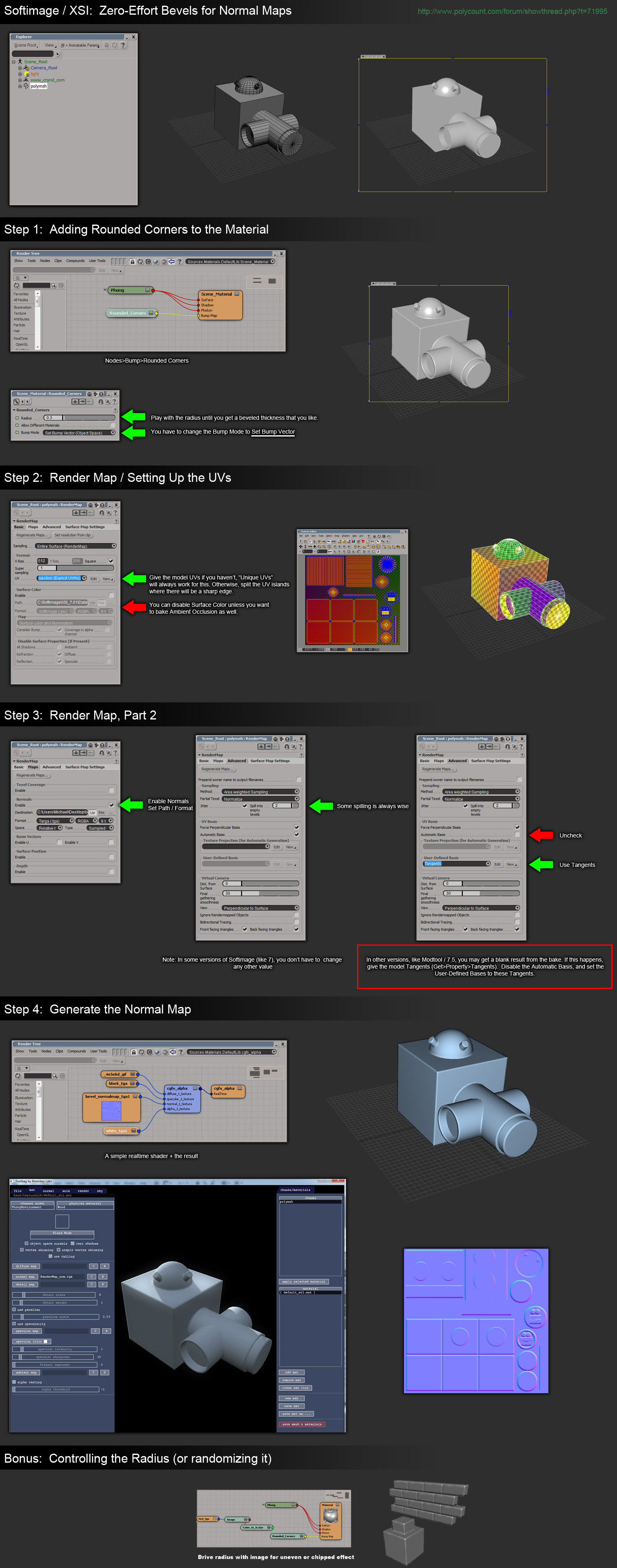
XSI is able to bake a good normal map with it, but 3ds Max seems to bake it incorrectly, and Maya isn't able to bake the effect at all. Maybe Max might be able to bake it correctly, if the .mi shader is edited to use the correct coordinate space?
Baking
The process of transferring normals from the high-res model to the in-game model is often called baking. The baking tool usually starts projecting a certain numerical distance out from the low-poly mesh, and sends rays inwards towards the high-poly mesh. When a ray intersects the high-poly mesh, it records the mesh's surface normal and saves it in the normal map.
To get an understanding of how all the options affect your normal map, do some test bakes on simple meshes like boxes. They generate quickly so you can experiment with UV mirroring, smoothing groups, etc. This helps you learn the settings that really matter.
- The tutorial Modeling High/Low Poly Models for Next Gen Games by João "Masakari" Costa has more examples of ray-casting, plus how to get better results from the bake.
Reset Transforms
Before baking, make sure your low-poly model's transforms have been reset. This is very important! Often during the modeling process a model will be rotated and scaled, but these compounded transforms can create a messy local "space" for the model, which in turn often creates rendering errors for normal maps.
In 3ds Max, use the Reset Xforms utility then Collapse the Modifier Stack. In Maya use Freeze Transformation. In XSI use the Freeze button.
Triangulating
Before baking, it is usually best to triangulate the low-poly model, converting it from polygons into pure triangles. This prevents the vertex normals from being changed later on, which can create specular artifacts.
Sometimes a baking tool or a mesh exporter/importer will re-triangulate the polygons. A quad polygon is actually treated as two triangles, and the internal edge between them is often switched diagonally during modeling operations. When the vertices of the quad are moved around in certain shapes, the software's algorithm for polygon models tries to keep the quad surface in a "rational" non-overlapping shape. It does this by switching the internal edge between its triangles.
<<Anchor(WorkingWithCages)>>
Working with Cages
Cage has two meanings in the normal-mapping process: a low-poly base for subdivision surface modeling (usually called the basemesh), or a ray-casting mesh used for normal map baking. This section covers the ray-casting cage.
Most normal map baking tools allow you to use a distance-based raycast. A ray is sent outwards along each vertex normal, then at the distance you set a ray is cast back inwards. Where ever that ray intersects the high poly mesh, it will sample the normals from it.
| File:NormalMap$Normalmap raycasting 1.jpg |
| Hard edges and a distance-based raycast (gray areas) cause ray misses (yellow) and ray overlaps (cyan).< >image byDiego Castaño |
Unfortunately with a distance-based raycast, split vertex normals will cause the bake to miss parts of the high-res mesh, causing errors and seams.
Some software allows you to use cage mesh option instead, which basically inflates a copy of the low-poly mesh, then raycasts inwards from each vertex. This ballooned-out mesh is the cage.
In 3ds Max the cage controls both the distance and the direction of the raycasting.
In Maya the cage only controls the distance; the ray direction matches the vertex normals (inverted).
This may have been fixed in the latest release...<
>
In Xnormal the cage is split everywhere the model has hard edges, causing ray misses in the bake. You can fix the hard edge split problem but it involves an overly complex workflow. You must also repeat the whole process any time you change your mesh:
-
Load the 3d viewer. -
Turn on the cage editing tools. -
Select all of the vertices. -
Weld all vertices. -
Expand the cage as you normally would. -
Save out your mesh using the Xnormal format. -
Make sure Xnormal is loading the correct mesh.
<<Anchor(SolvingIntersections)>>
Solving Intersections
The projection process often causes problems like misses, or overlaps, or intersections. It can be difficult generating a clean normal map in areas where the high-poly mesh intersects or nearly intersects itself, like in between the fingers of a hand. Setting the ray distance too large will make the baker pick the other finger as the source normal, while setting the ray distance too small will lead to problems at other places on the mesh where the distances between in-game mesh and high-poly mesh are greater.
Fortunately there are several methods for solving these problems.
- Change the shape of the cage. Manually edit points on the projection cage to help solve tight bits like the gaps between fingers.
- Limit the projection to matching materials, or matching UVs.
- Explode the meshes. See the polycount thread Explode script needed (for baking purposes).
- Bake two or more times using different cage sizes, and combine them in Photoshop.
<<Anchor(SolvingWavyLines)>>
Solving Wavy Lines
When capturing from a cylindrical shape, often the differences between the low-poly mesh and the high-poly mesh will create a wavy edge in the normal map. There are a couple ways to avoid this:
- Adjust the shape of the cage to influence the directions the rays will be cast. At the bottom of this page of his normal map tutorial, Ben "poopinmymouth" Mathis shows how to do this in 3ds Max. Same method can be seen in the image below.
- Subdivide the low-res mesh so it more closely matches the high-res mesh. Jeff "airbrush" Ross has a video tutorial that shows how to do this in Maya.
- Paint out the wavy line. The normal map process tutorial by Ben "poopinmymouth" Mathis includes an example of painting out wavy lines in a baked normal map.
- Use a separate planar-projected mesh for the details that wrap around the barrel area, so the ray-casting is more even. For example to add tread around a tire, the tread can be baked from a tread model that is laid out flat, then that bake can layered onto the bake from the cylindrical tire mesh in a paint program.
- The polycount thread "approach to techy stuff" has some good tips for normal-mapping cylindrical shapes.
<<Anchor(SolvingPixelArtifacts)>>
Solving Pixel Artifacts
If you are using 3ds Max's Render To Texture to bake from one UV layout to another, you may see stray pixels scattered across the bake. This only happens if you are using a copy of the original mesh in the Projection, and that mesh is using a different UV channel than the original mesh.
There are two solutions for this:
- Add a Push modifier to the copied mesh, and set it to a low value like 0.01.
- or -
- Turn off Filter Maps in the render settings (Rendering menu > Render Setup > Renderer tab > uncheck Filter Maps). To prevent aliasing you may want to enable the Global Supersampler in Render Setup.
<<Anchor(BakingTransparency)>>
Baking Transparency
Sometimes you need to bake a normal map from an object that uses opacity maps, like a branch with opacity-mapped leaves. Unfortunately baking apps often completely ignore any transparency mapping on your high-poly mesh.
| File:NormalMap$JoeWilson ivynormals error.jpg |
| 3ds Max's RTT baker causes transparency errors.< >image byJoe "EarthQuake" Wilson |
To solve this, render a Top view of the mesh. This only works if you're using a planar UV projection for your low-poly mesh and you're baking a tangent-space normal map.
- Make sure the Top view matches the dimensions of the planar UV projection used by the low-poly mesh. It helps to use an orthographic camera for precise placement.
- On the high-poly mesh either use a specific lighting setup or a use special material shader:
- 1) The lighting setup is described in these tutorials:
- * Creating A Normal Map Right In Your 3D App by Ben Cloward
- *Generating High Fidelity Normal Maps with 3-D Software by Dave McCoy, Graphics Techniques Consultant, Xbox Content and Design Team
- 2) The material shader does the same thing, but doesn't require lights.
- * NormalTexMap scripted map for 3ds Max by Dave Locke.
- * InfoTexture map plugin for 3ds Max by John Burnett
<<Anchor(AntiAliasing)>>
Anti-Aliasing
Turning on super-sampling or anti-aliasing (or whatever multi-ray casting is called in your normal map baking tool) will help to fix any jagged edges where the high-res model overlaps itself within the UV borders of the low-poly mesh, or wherever the background shows through holes in the mesh. Unfortunately this tends to render much much slower, and takes more memory.
One trick to speed this up is to render 2x the intended image size then scale the normal map down 1/2 in a paint program like Photoshop. The reduction's pixel resampling will add anti-aliasing for you in a very quick process. After scaling, make sure to re-normalize the map if your game doesn't do that already, because the un-normalized pixels in your normalmap may cause pixelly artifacts in your specular highlights. Re-normalizing can be done with NVIDIA's normal map filter for Photoshop.
3ds Max's supersampling doesn't work nicely with edge padding, it produces dark streaks in the padded pixels. If so then turn off padding and re-do the padding later, either by re-baking without supersampling or by using a Photoshop filter like the one that comes with Xnormal.
<<Anchor(EdgePadding)>>
Edge Padding
If a normal map doesn't have enough Edge Padding, this will create shading seams on the UV borders.
Painting
Don't be afraid to edit normal maps in Photoshop. After all it is just a texture, so you can clone, blur, copy, blend all you want... as long as it looks good of course. Some understanding of the way colors work in normal maps will go a long way in helping you paint effectively.
A normal map sampled from a high-poly mesh will nearly always be better than one sampled from a texture, since you're actually grabbing "proper" normals from an accurate, highly detailed surface. That means your normal map's pixels will basically be recreating the surface angles of your high-poly mesh, resulting in a very believable look.
If you only convert an image into a normal-map, it can look very flat, and in some cases it can be completely wrong unless you're very careful about your value ranges. Most image conversion tools assume the input is a heightmap, where black is low and white is high. If you try to convert a diffuse texture that you've painted, the results are often very poor. Often the best results are obtained by baking the large and mid-level details from a high-poly mesh, and then combined with photo-sourced "fine detail" normals for surface details such as fabric weave, scratches and grain.
Sometimes creating a high poly surface takes more time than your budget allows. For character or significant environment assets then that is the best route, but for less significant environment surfaces working from a heightmap-based texture will provide a good enough result for a much less commitment in time.
- CrazyBump is a commercial normal map converter.
- ShaderMap is a commercial normal map converter.
- PixPlant is a commercial normal map converter.
- NJob is a free normal map converter.
- NVIDIA normalmap filter for Photoshop is a free normal map converter.
- Xnormal height-to-normals filter for Photoshop is a free normal map converter.
- Normal map process tutorial by Ben "poopinmymouth" Mathis includes an example of painting out wavy lines in a baked normal map.
<<Anchor(BlendingNormalMapsTogether)>>
Blending Normal Maps Together
Blending normal maps together is a quick way to add high-frequency detail like wrinkles, cracks, and the like. Fine details can be painted as a height map, then it can be converted into a normal map using one of the normal map tools. Then this "details" normal map can be blended with a geometry-derived normal map using one of the methods below.
Here is a comparison of four of the blending methods. Note that in these examples the default values were used for CrazyBump (Intensity 50, Strength 33, Strength 33), but the tool allows each layer's strength to be adjusted individually for stronger or milder results. Each of the normal maps below were re-normalized after blending.
| [[Image:NormalMap$nrmlmap_blending_methods_Maps.png}} |
| The blended normal maps.< >image byEric Chadwick |
The four blending methods used above:
- CrazyBump by Ryan Clark blends normal maps together using calculations in 3D space rather than just in 2D. This does probably the best job at preserving details, and each layer's strength settings can be tweaked individually.
- Combining Normal Maps in Photoshop by Rod Green blends normal maps together using Linear Dodge mode for the positive values and Difference mode for the negative values, along with a Photoshop Action to simplify the process. It's free, but the results may be less accurate than CrazyBump.
- Making of Varga by Paul "paultosca" Tosca blends normal maps together using Overlay mode for the red and green channels and Multiply mode for the blue channel. This gives a slightly stronger bump than the Overlay-only method. Leo "chronic" Covarrubias has a step-by-step tutorial for this method in CG Bootcamp Combine Normal Maps.
- Normalmap Deepening by Ben "poopinmymouth" Mathis shows how to blend normal maps together using Overlay mode. CGTextures tutorial for the NVIDIA Photoshop filter by Scott Warren also shows how to create normalmaps using multiple layers (Note: to work with the Overlay blend mode each layer's Output Level should be 128 instead of 255, you can use the Levels tool for this).
The Getting good height from Nvidia-filter normalizing grayscale height thread on the Polycount forum has a discussion of different painting/blending options. Also see the 2D Tools section for painting and conversion tools.
Pre-Created Templates
A library of shapes can be developed and stored for later use, to save creation time for future normal maps. Things like screws, ports, pipes, and other doo-dads. These shapes can be stored as bitmaps with transparency so they can be layered into baked normal maps.
- Creating & Using NormalMap "Widgets" - by Steev "kobra" Kelly<
> How to set up and render template objects. - NormalMap Widget for 3ds Max - by Akram Parvez<
>A script to automate the setup and rendering process. - See the section Baking Transparency for more template-rendering tools and tutorials.
Re-normalizing
Re-normalizing means resetting the length of each normal in the map to 1.
A normal mapping shader takes the three color channels of a normal map and combines them to create the direction and length of each pixel's normal. These normals are then used to apply the scene lighting to the mesh. However if you edit normal maps by hand or if you blend multiple normal maps together this can cause those lengths to change. Most shaders expect the length of the normals to always be 1 (normalized), but some are written to re-normalize the normal map dynamically (for example, 3ds Max's Hardware Shaders do re-normalize).
If the normals in your normal map are not normalized, and your shader doesn't re-normalize them either, then you may see artifacts on the shaded surface... the specular highlight may speckle like crazy, the surface may get patches of odd shadowing, etc. To help you avoid this NVIDIA's normal map filter for Photoshop provides an easy way to re-normalize a map after editing; just use the Normalize Only option. Xnormal also comes with a Normalize filter for Photoshop.
Some shaders use compressed normal maps. Usually this means the blue channel is thrown away completely, so it's recalculated on-the-fly in the shader. However the shader has to re-normalize in order to recreate that data, so any custom normal lengths that were edited into the map will be ignored completely.
Ambient Occlusion into a Normal Map
If the shader doesn't re-normalize the normal map, an Ambient Occlusion Map can actually be baked into the normal map. This will shorten the normals in the crevices of the surface, causing the surface to receive less light there. This works with both diffuse and specular, or any other pass that uses the normal map, like reflection.
To bake the AO into a normal map, adjust the levels of the AO layer first so the darks only go as low as 127 gray, then set the AO layer to Darken mode. This will shorten the normals in the normalmap, causing the surface to receive less light in the darker areas.
This trick doesn't work with any shaders that re-normalize, like 3ds Max's Hardware Shaders. The shader must be altered to actually use the lengths of your custom normals; most shaders just assume all normals are 1 in length because this makes the shader code simpler. Also this trick will not work with most of the common normal map compression formats, which often discard the blue channel and recalculate it in the shader, which requires re-normalization.
For the best results it's usually best to multiply AO into the color map instead of editing it into the normal map.
<<Anchor(BacklightingExample)>>
Back Lighting Example
You can customize normal maps for some interesting effects. If you invert the blue channel of a tangent-space map, the normals will be pointing to the opposite side of the surface, which can simulate backlighting.
| File:NormalMap$tree front.jpg |
| Tree simulating subsurface scattering (front view).< >image byEric Chadwick |
The tree leaves use a shader than adds together two diffuse maps, one using a regular tangent-space normal map, the other using the same normal map but with the blue channel inverted. This causes the diffuse map using the regular normal map to only get lit on the side facing the light (front view), while the diffuse map using the inverted normal map only gets lit on the opposite side of the leaves (back view). The leaf geometry is 2-sided but uses the same shader on both sides, so the effect works no matter the lighting angle. As an added bonus, because the tree is self-shadowing the leaves in shadow do not receive direct lighting, which means their backsides do not show the inverted normal map, so the fake subsurface scatter effect only appears where the light directly hits the leaves. This wouldn't work for a whole forest because of the computational cost of self-shadowing and double normal maps, but could be useful for a single "star" asset, or if LODs switched the distant trees to a model that uses a cheaper shader.
<<Anchor(ShadersAndSeams)>>
Shaders and Seams
You need to use the right kind of shader to avoid seeing seams where UV breaks occur. It must be written to use the same tangent basis that was used during baking. If the shader doesn't, the lighting will either be inconsistent across UV borders or it will show smoothing errors from the low-poly vertex normals.
Xnormal generates accurate normals when displayed in Xnormal, and the SDK includes a method to write your own custom tangent space generator for the tool.
3ds Max Shaders
The "Render To Texture" tool in 3ds Max 2011 and older generates tangent-space normal maps that render correctly in the offline renderer (scanline) but do not render correctly in the realtime viewport with the 3ds Max shaders. Max is using a different tangent basis for each. This is readily apparent when creating non-organic hard surface normalmaps; smoothing errors appear in the viewport that do not appear when rendered.
The errors can be fixed by using "Render To Texture" to bake a tangent-space or object-space map, and using the free "3Point Shader" by Christoph 'CrazyButcher' Kubisch and Per 'perna' Abrahamsen. The shader uses the same tangent basis as the baking tool, so it produces nearly flawless results. It also works with old bakes.
You can get OK results in the Max viewport using a tangent-space map baked in Maya, loading it in a Standard material, and enabling "Show Hardware Map in Viewport". Another method is to use Render To Texture to bake an object-space map then use Nspace to convert it into a tangent-space map then load that in a DirectX material and use the RTTNormalMap.fx shader.
Autodesk is aware of these issues, and plans to address them in an upcoming release. See these links for more information:
- Christoph "CrazyButcher" Kubisch and Per "perna" Abrahamsen designed a shader/modifier combination approach that fixes the viewport problem, see the Polycount forum post 3Point Shader Lite - Shader material editor and Quality Mode normalmaps for 3ds Max.
- Jean-Francois "jfyelle" Yelle, Autodesk Media & Entertainment Technical Product Manager, has this post.
- Ben Cloward posted workarounds and FX code.
- Christopher "cdiggins" Diggins, SDK writer for 3ds Max, shares some of the SDK code in his blog posts "How the 3ds Max Scanline Renderer Computes Tangent and Binormal Vectors for Normal Mapping" and "3ds Max Normal Map Baking and Face Angle Weighting: The Plot Thickens".
| File:NormalMap$max2010 normalmap workarounds thumb.png |
| Viewport methods in 3ds Max 2010.< >Actual size< >image by Eric Chadwick |
3ds Max Edit Normals Trick
After baking, if you add an Edit Normals modifier to your low-poly normalmapped model, this seems to "relax" the vertex normals for more accurate viewport shading. The modifier can be collapsed if desired.
Maya Shaders
Maya seems to correctly generate normals to view in realtime, with the correct tangent basis, with much less smoothing errors than 3ds Max.
- BRDF shader by Brice Vandemoortele and Cedric Caillaud (more info in this Polycount thread) Update: New version here with many updates, including object-space normal maps, relief mapping, self-shadowing, etc. Make sure you enable cgFX shaders in the Maya plugin manager, then you can create them in the same way you create a Lambert, Phong etc. Switch OFF high quality rendering in the viewports to see them correctly too.
- If you want to use the software renderer, use mental ray instead of Maya's software renderer because mental ray correctly interprets tangent space normals. The Maya renderer treats the normal map as a grayscale bump map, giving nasty results. Mental ray supports Maya's Phong shader just fine (amongst others), although it won't recognise a gloss map plugged into the "cosine power" slot. The slider still works though, if you don't mind having a uniform value for gloss. Spec maps work fine though. Just use the same set up as you would for viewport rendering. You'll need to have your textures saved as TGAs or similar for mental ray to work though. - from CheeseOnToast
<<Anchor(NormalMapCompression)>>
Normal Map Compression
Normal maps can take up a lot of memory. Compression can reduce the size of a map to 1/4 of what it was uncompressed, which means you can either increase the resolution or you can use more maps.
Usually the compression method is to throw away the Blue channel, because this can be re-computing at minimal cost in the shader code. Then the bitmap only has to store two color channels, instead of four (red, green, blue, and alpha).
- The article Real-Time Normal Map DXT Compression from id software and NVIDIA is an excellent introduction to compression.
DXT5nm Compression
DXT5nm is the same file format as DXT5 except before compression the red channel is moved into the alpha channel, the green channel is left as-is, and the red and blue channels are blanked with the same solid color. This re-arranging of the color channels is often called swizzling.
The Green and Alpha channels are used because in the DXT format they are compressed using somewhat higher bit depths than the Red and Blue channels. Red and Blue have to be filled with the same solid color because DXT uses a compression system that compares differences between the three color channels. If you try to store some kind of texture in Red and/or Blue (specular power, height map, etc.) then the compressor will create more compression artifacts because it has to compare all three channels.
There are some options in the NVIDIA DXT compressor that help reduce the artifacts if you want to add texture to the Red or Blue channels. The artifacts will be greater than if you keep Red and Blue empty, but it might be a tradeoff worth making. Some notes about this on the NVIDIA Developer Forums.
DXT1 Compression
DXT1 is also used sometimes for tangent-space normal maps, because it is half the size of a DXT5. The downside though is that it causes many more compression artifacts, so much so that most people end up not using it.
- The blog post I like spilled beans! by Christer Ericson has a section about Capcom's clever use of DXT1 and DXT5.
3DC Compression
3Dc compression works similar to DXT5nm, with some important differences. It yields the best results of any listed algorithm for tangent space normal map compression, and requires no extra processing time or unique hardware. Details can be found in the3Dc whitepaper from ATI.
A8L8 Compression
The DDS format !A8L8 isn't actually compressed, it's just two 8bit grayscale channels (256 grays each). It does save you from having to store all three color channels. Your shader has to recompute the blue channel for it to work. However, !A8L8 does not actually save any space in texture memory, it is typically converted to a four-channel 32bit texture when it's sent to the card. This format really only helps save disk space.
Links
3D Tools
- The major 3D apps (3ds Max, Blender, Cinema 4D, Maya, XSI) and dedicated 3D sculpting tools (Modo, Mudbox, ZBrush) each have their own integrated normal map baking tools.
- xNormal by Santiago Orgaz & collaborators is a free application to generate normal, ambient occlusion, parallax displacement, and relief maps. It can also project the texture of the highpoly model into the lowpoly mesh, even with different topologies. It includes an interactive 3D viewer with multiple mesh and textures format support, shaders, realtime soft shadows, and glow effect. It also includes useful tools like height map, normal map, cavity map, occlusion map, and tangent-space/object-space conversion.
- Turtle by Illuminate Labs is a commercial baking and rendering plugin for Maya.
- SHTools for UE3 (restricted access) is a baking application included with Unreal Engine 3.
- PolyBump2 by Crytek is a baking application included with CryEngine2.
- Renderbump by id software is a baking application included with Doom 3.
- Kaldera by Mankua is a commercial baking plugin for 3ds Max, but it hasn't been updated since 2005.
- Melody by NVIDIA is a free baking application, but it hasn't been updated since 2005.
- NormalMapper by ATI/AMD is a free baking application, but it hasn't been updated since 2004.
- ORB (Open Render Bump) by Martin Fredriksson and C. Seger is a free baking application, but it hasn't been updated since 2003.
2D Tools
- Crazy Bump by Ryan Clark is a commercial tangent-space normal map converter for 2D images. It is very likely the best and the fastest of them all. It also creates displacement maps, specular maps, fixes problems with diffuse maps, layers multiple normal maps, etc.
- ShaderMap by Rendering Systems is a commercial normal map converter for photos and displacement maps. It has a free command-line version and a low-cost GUI version.
- PixPlant is a commercial normal map converter.
- NJob is a free normal map converter.
- Xnormal height-to-normals filter for Photoshop is a free normal map converter.
- NVIDIA normal map filter is a free tangent-space normal map converter for 2D images. A filter for Photoshop, it also re-normalizes, converts to height, and creates [[[DuDv|Map]]]s.
- NVIDIA DDS texture compression plugin for Photoshop is also free, and has the same options as the NVIDIA normal map filter. Additionally it lets you create the best-quality Mip Maps for a normal map, by filtering each mip independently from the original source image, rather than simply scaling down the normal map.
- GIMP normalmap plugin is a free plugin by Shawn Kirst.
- NSpace is a free convert from Diogo Teixeira that can convert Object Space normal maps into Tangent Space normal maps. The tool is discussed in this thread and Osman "osman" Tsjardiwal has created GUI for it as well.
- Normal Map Actions for Photoshop by Will "sinistergfx" Fuller<
>• Overlay: Levels blue channel of current layer to 127 and sets the blend mode to overlay. Used for overlaying additional normal map detail.<
>• Normalize: Just does a nVidia normal map filter normalize on the current layer.<
>• Normalize (flatten): Flattens the image and does a nVidia normal map filter normalize.<
>• Rotate 90 CW: Rotates current normal map layer 90 degrees clockwise and fixes your red and green channels so that it doesn't break your normal map.<
>• Rotate 90 CW (inverted Y): Rotates current normal map layer 90 degrees clockwise and fixes your red and green channels so that it doesn't break your normal map. For normal maps that use the inverted Y convention.<
>• Rotate 90 CCW: Rotates current normal map layer 90 degrees counter-clockwise and fixes your red and green channels so that it doesn't break your normal map.<
>• Rotate 90 CCW (inverted Y): Rotates current normal map layer 90 degrees counter-clockwise and fixes your red and green channels so that it doesn't break your normal map. For normal maps that use the inverted Y convention.<
>• Rotate 180: Rotates current normal map layer 180 degrees and fixes your red and green channels so that it doesn't break your normal map.
Tutorials
- Renderbump and baking normal maps from high poly models using Blender 3D by "katsbits"<
>Baking normal maps in Blender. - How to Bake a Flawless Normal Map in 3ds Max by "racer445"<
> Overall a great intro, but there are a lot of misconceptions. - Techniques for Creating Normal Maps in the Unreal Developer Network's Unreal Engine 3 section contains advice from Epic Games artists on creating normal maps for UE3. The Design Workflow page has a summary.
- Creating Models in Quake 4 by Raven Software is a comprehensive guide to creating Quake 4 characters.
- Normalmaps for the Technical Game Modeler by Ariel Chai shows how low-poly smoothing and UVs can affect normal maps in Doom 3.
- Modeling High/Low Poly Models for Next Gen Games by João "Masakari" Costa is an overview of modeling for normal maps.
- The Beveling section on the Tech-Artists.Org Wiki discusses how smoothing groups and bevels affect the topology of the low-poly model.
- The two-part article Beautiful, Yet Friendly by Guillaume Provost explains how smoothing groups and other mesh attributes cause vertices to be duplicated in the game. The vertex count is actually what matters in-game, not the triangle or poly count.
- Normal map workflow by Ben "poopinmymouth" Mathis demonstrates his normal mapping workflow in 3ds Max and Photoshop.
- This video tutorial by Jeff "airbrush" Ross shows in Maya how to subdivide the low-poly mesh so it more closely matches the high-poly mesh, to help solve wavy lines in the bake.
- Normal Mapping Tutorial by Ben Cloward is a comprehensive tutorial about the entire normal map creation process.
- Generating High Fidelity Normal Maps with 3-D Software by Dave McCoy shows how to use a special lighting setup to render normal maps (instead of baking them).
- Tutorial for the NVIDIA Photoshop filter by Scott Warren shows how to create deep normal maps using multiple layers. Note: to use Overlay blend mode properly, make sure to change each layer's Levels Output Level to 128 instead of 255.
- Normalmap Deepening by Ben "poopinmymouth" Mathis shows how to adjust normal maps, and how to layer together painted and baked normal maps.
- Tutorial for painting out seams on mirrored tangent-space normal maps by warby helps to solve seams along horizontal or vertical UV edges, but not across angled UVs.
- Cinema 4D and Normal Maps For Games by James Hastings-Trew describes normal maps in plain language, with tips on creating them in Cinema 4D.
- 3ds Max normal mapping overview by Alan Noon is a great thread on CGTalk about the normal mapping process.
- Hard Surface Texture Painting by Stefan Morrell is a good introduction to painting textures for metal surfaces.
Discussion
Discuss this page on the Polycount forums. Suggestions welcome.
Even though only one person has been editing this page so far, the information here was gathered from many different sources. We wish to thank all the contributors for their hard-earned knowledge. It is much appreciated! Template:Http://boards.polycount.net/images/smilies/pcount/icons/smokin.gif
<
>
- Main Page > > Normal Map